• Welcome, Guest! We hope you enjoy the excellent technical knowledge, event information and discussions that the BMW MOA forum provides. Some forum content will be hidden from you if you remain logged out. If you want to view all content, please click the 'Log in' button above and enter your BMW MOA username and password.

    If you are not an MOA member, why not take the time to join the club, so you can enjoy posting on the forum, the BMW Owners News magazine, and all of the discounts and benefits the BMW MOA offers?

Stebel Horn Install on a KGT 1300

Semper_Fi

Honey Badger
The articles, posts and comments in this tech section are posted by individual members and reflect their personal thoughts and experiences with repairing, maintaining, and generally working on motorcycles. This information may require specific knowledge and skills, may or may not be correct or current to model.

The authors of information found here and the BMW MOA take no responsibility for ensuring the accuracy of any information (including procedures, techniques, parts numbers, torque values, tool usage, etc.), or further for any damage of any kind or injuries incurred or caused by anyone following the instructions or information found here.

It is the duty of the individual to either assume the liability himself for responsibly using the information found here, or to take the bike or accessory to a Dealer or other qualified professional service.


Lastly, please ensure you dispose of your used chemicals, oils and fuels in an environmentally responsible manner. Most Auto Parts stores and service stations will accept used oil and lubricants, tires and batteries, please check for your local availability.


This article, text and photos are Copyright of the individual authors and the BMW MOA, any copying or redistributing is permitted only by prior written authorization.
 
This DYI describes how to mount a Stebel Horn on a KGT 1300.

The Horn and Mount Kit was obtained from http://www.excelcyclewerkes.com/
(No affiliation, just used his product)

Other reference material in addtion to the provided installation instructions is this pictorial from the werks site link

I reviewed the instructions and documented the process of installation.

The Scope of Work entails the following:

  • Remove Left/Right/Top Fairing Plastics
  • Remove air intake snorkel and access horn connection
  • Prep Mounting bracket and area for compressor
  • Mount horn
  • Wire relay and compressor
  • Dress wire harnesses
  • Test
  • Re-assemble

Special Note - I have a Centech Fuse Panel so I did not mount the provided fuse carrier and fuse.
 
Last edited:
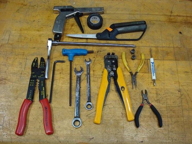
Tools Used

Below is the display of tools used.

You do not need the exact ones - it's just the ones I used:

- Zip Tie Gun
- Friction Tape
- Scissors
- 1/4 in drive ratchet and extension
- Crimp Tool
- 5mm Hex
- 5 mm Hex with handle
- 13mm wrench
- 10mm wrench
- wire strippers
- T30/25 Sockets
- Needle nose pliers
- snips
- small combo screw driver
 

Attachments

  • 0 Tools.jpg
    0 Tools.jpg
    128.3 KB · Views: 458
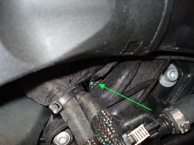
Accessing the Horn connection

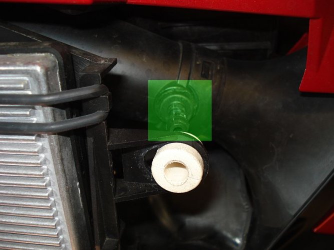
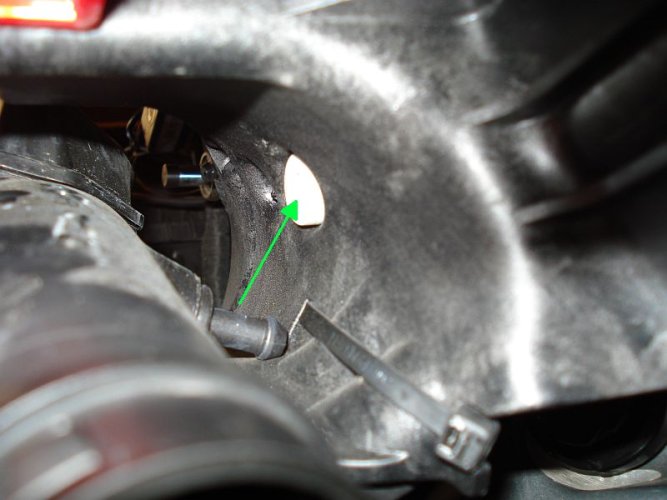
The green arrow highlights the location of the horn connector you need to access to set up the trigger for the air horn.

This is on the throttle side of the bike, below the mid way point of the air snorkle intake.

As it is so conjested I decided to remove the air snorkle intake for access.
 

Attachments

  • 1 Horn ConnectionLocation.jpg
    1 Horn ConnectionLocation.jpg
    107.3 KB · Views: 467
Last edited:
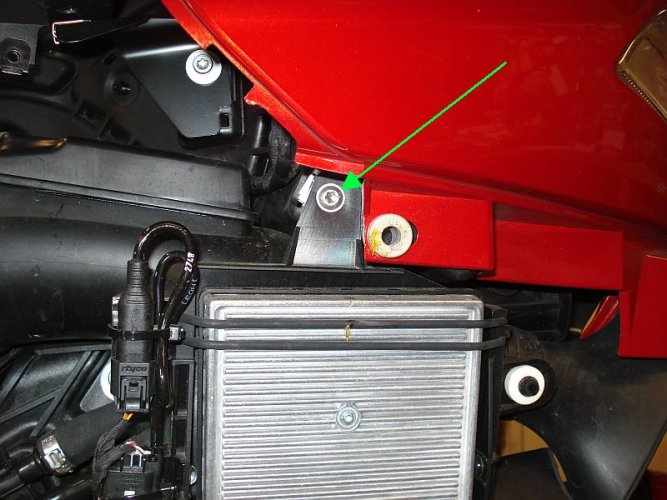
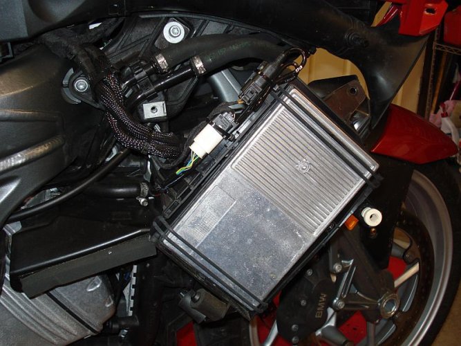
The computer needs to be unmounted and set out of the way.

There are two screws and one clip on mount.

The first is shown below
 

Attachments

  • 2 Computer screw 2.jpg
    2 Computer screw 2.jpg
    106.5 KB · Views: 466
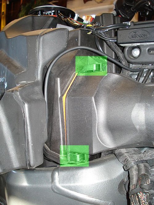
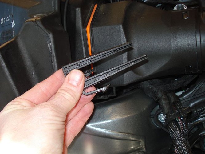
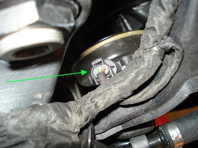
Remove the snorkle from the bike frame.

Please note detail of connection - you will need to give a good steady tug to pull off.
 

Attachments

  • 8 Air Snorkel Connection.jpg
    8 Air Snorkel Connection.jpg
    68.6 KB · Views: 458
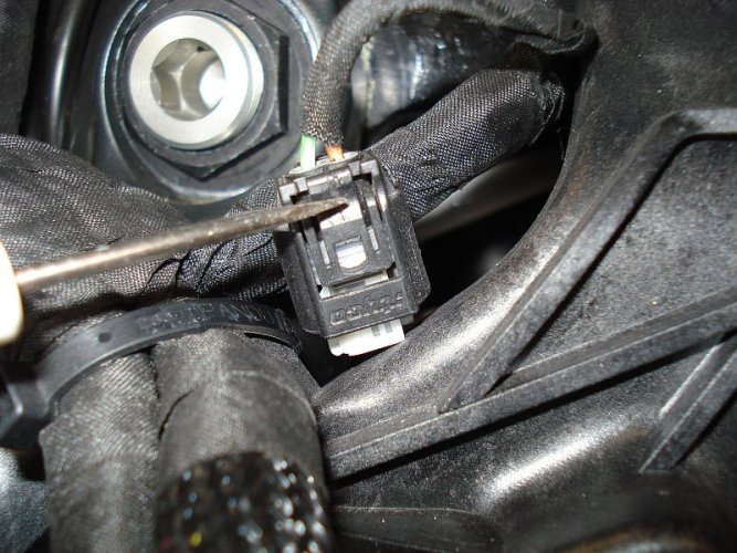
The picture below shows how I removed the connector by pressing with the screwdriver in the tab as shown.

Please note that the connector is clipped in place so that it not strong enough to withstand the pressure of pressing on the tab - support the connector from the back with one hand while working the tab to disconnect.
 

Attachments

  • 10 Horn Connector Removal.jpg
    10 Horn Connector Removal.jpg
    132.9 KB · Views: 482
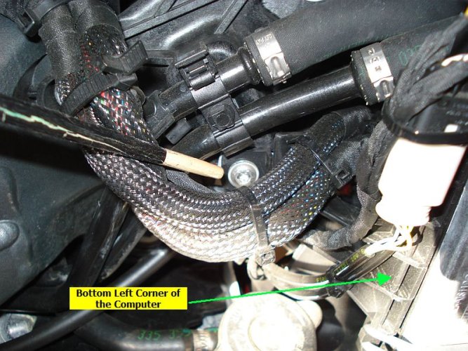
Prepping the Compressor Mounting Area

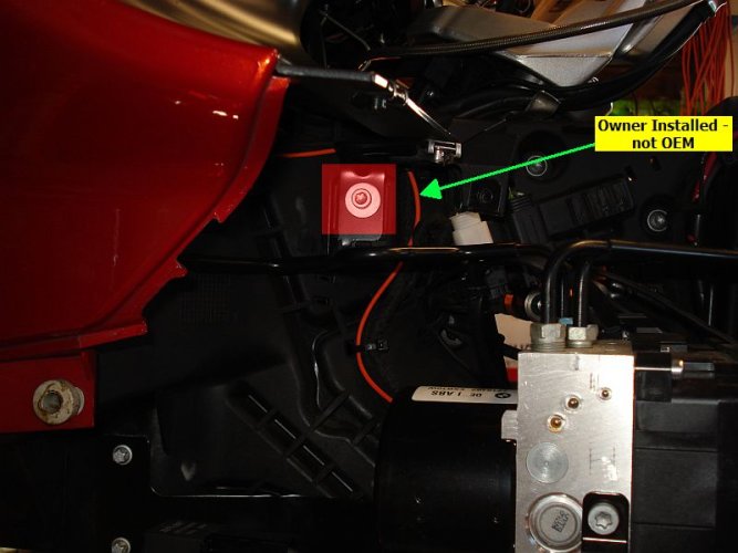
Location is now on the Clutch side of the bike.

The red highlighted area is the screw to remove it is a T30 torx.

The ornage wire is my trigger wire for the centech, it is not part of the standard bike.
 

Attachments

  • 11 Bracket Screw Location .jpg
    11 Bracket Screw Location .jpg
    72.9 KB · Views: 463
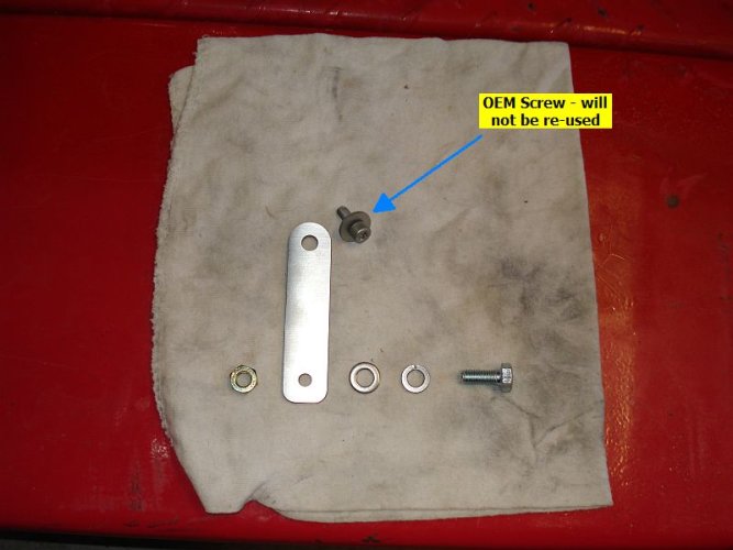
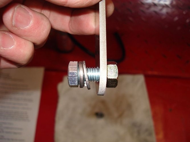
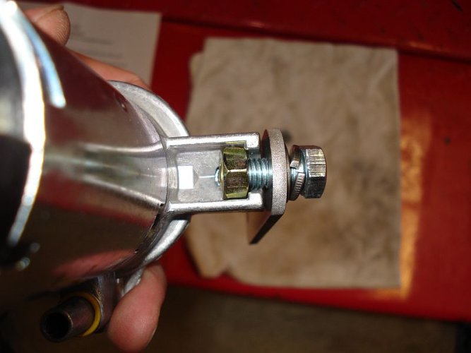
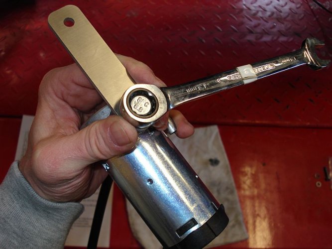
Shown the mounting bracket from the kit, the 8mm bolt (13mm wrench) lock washer, regular washer and nut.

The OEM Torx bolt will not be used and it will be replaced with new supplied hardware.
 

Attachments

  • 12 Bracket Hardware.jpg
    12 Bracket Hardware.jpg
    63.5 KB · Views: 260
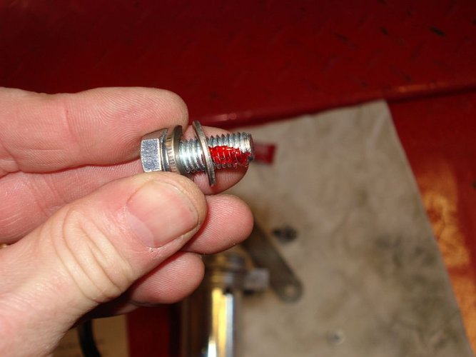
Anal retentiveness alert - locktighted the screw - not required
 

Attachments

  • 14 Bracket Hardware 3.jpg
    14 Bracket Hardware 3.jpg
    58 KB · Views: 259
Last edited:
Back
Top