• Welcome, Guest! We hope you enjoy the excellent technical knowledge, event information and discussions that the BMW MOA forum provides. Some forum content will be hidden from you if you remain logged out. If you want to view all content, please click the 'Log in' button above and enter your BMW MOA username and password.

    If you are not an MOA member, why not take the time to join the club, so you can enjoy posting on the forum, the BMW Owners News magazine, and all of the discounts and benefits the BMW MOA offers?

  • Beginning April 1st, and running through April 30th, there is a new 2024 BMW MOA Election discussion area within The Club section of the forum. Within this forum area is also a sticky post that provides the ground rules for participating in the Election forum area. Also, the candidates statements are provided. Please read before joining the conversation, because the rules are very specific to maintain civility.

    The Election forum is here: Election Forum

Mounting /5 flasher relay

S

sneakers563

Guest
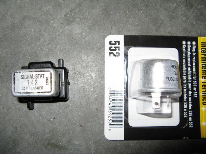
I think I have a bad flasher relay on my '71 R75/5. I've pulled the old one out (pictured on left, below). I have no idea if it's original to the bike or not. I brought it to NAPA and Checker and neither one could find a Signal-Stat 142. What they could find was a NAPA 552 (pictured on right, below), which I've seen suggested as a replacement in another thread.

My problem, though, is that I don't really know how to mount the 552. The 552 is obviously quite a different shape from the 142, but it does look like the one pictured in the Clymer manual and on the various BMW parts fiches (which makes me think the 142 is not original). The old relay mounted by way of a screw and rubber spacer through the bottom, but there's nothing similar on the 552.

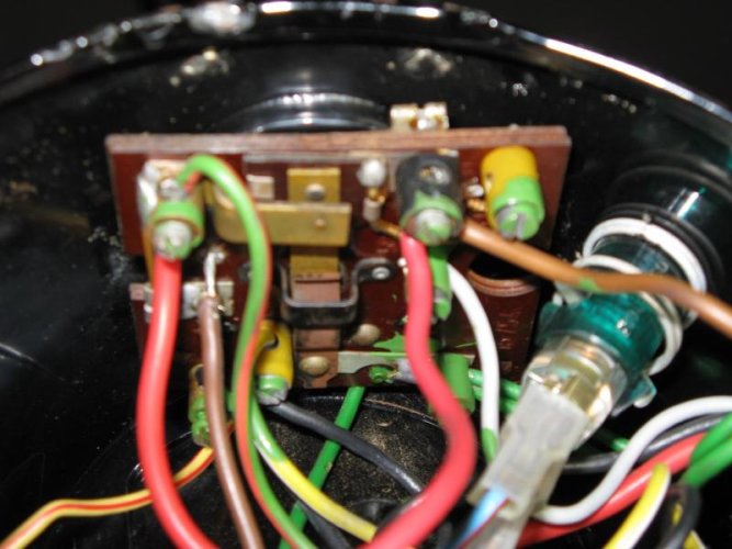
So, those of you with /5's, how is the can-style flasher relay mounted? Is there a socket that it plugs into? Is that what part #63128650145 is? Or does it strap/screw into the mounting bracket on the right side of the headlight bucket? Or is it something else entirely?

Thanks for any help!
 

Attachments

  • img_0726.jpg
    img_0726.jpg
    77 KB · Views: 132
Unplug the old relay from its mounting socket and the solution to
your problem will be obvious.
 
relay

it looks like the signal stat is still mounted on the connector plate. Pry the rectangular part off the black Hella base. You will then see the place where the three prongs on the new flasher go. As you know, from removing the signal stat from the headlight,you have to depress the spring held wire connectors to insert the wires into their respective numbered terminals. 31, 56 etc.
 
Thanks, I thought the old one was one piece, didn't realize the bottom part was the mounting bracket. Thanks!
 
More wiring woes

OK, here's the deal: this is all from a '71 /5 that I got cheap a few weeks ago. The bike's in decent shape, and the seller was the original owner. However, when I bought it, the bike hadn't been run in 7 years, and the owner had, over the years, made a few touring-type mods to it. There was a Windjammer IV fairing, twin air horns, a 100w headlight mod, extra relays to power the horns and headlight, a fuse added to the positive lead off the battery, Mikuni carbs (with a mod to the airbox sleeves).

Long story short: I'm trying to get it back to something close to stock. That's all gone pretty well, but the headlight is not working, and I'm having trouble figuring out the wiring. I think the original owner changed the wiring around a bit to accommodate the headlight relay and the fairing, and I don't have anything to compare the wiring to other than my Clymer manual.

So, would someone mind looking at the picture below and answering a couple of questions? I won't even speculate on why it looks like some parts were dipped in green paint, or why the big red wire in the center of the picture is grounded to the bracket for the flasher relay...

1) What is that brown wire just behind the top-left terminal that looks like it's soldered directly onto the board (the one with the insulation pulled back)? The other end has been taped off and wasn't connected to anything. Seeing that it was brown, I naturally assumed it was a ground (I figured for the headlight), but in all three positions of the key it has +12v relative to frame ground. I can't figure out where it should go.

2a) There are two yellow terminals (top right and mid-rear). The one on the top right has nothing connected to it. Should there be? If so, what?
2b) The mid-rear one has a single yellow/white wire connected to it that runs to the headlight switch. However, no position of the key puts any kind of voltage on it, and, as I've said, the headlight does not work. Is this the correct terminal for that wire? It looks like there should be at least 1 other wire connected to it going to the speedo and tach lights. Should there be anything else connected to it, perhaps to feed it juice?

I was really hoping to avoid doing too much wiring work, since everything but the headlight is working. But the fact that the yellow terminals don't ever seem to get any juice is worrying.
 

Attachments

  • img_0730.jpg
    img_0730.jpg
    60.9 KB · Views: 100
Not having a schematic here in front of me to figure it out and return it to stock; but that is what I suggest you do. Forget about what the PO did and return it back to what the guys in the fatherland designed and did originally. For me, trying to figure this stuff out is like trying to understand how a nuclear reactor functions. Give me a schematic though and it all falls into place..................Good Luck.......Dennis
 
Dennis -

I'm looking at the diagram and I'm not sure that helps!!

I think you should try to identify the terminal numbers on the ignition board to better understand what wires need to go where. My Haynes diagram shows the following:

30/51 - 2 wires -- red from pin 30 on starter relay; green w/ red from pin 30 on the horn/light dip switch

31 - 3 brown wires -- from pin 31 on turn signal/start button switch; parking lamp; frame ground

15 - 2 green wires -- from fuse block which has two green w/ black wires on the other side; the other wire to one side of the ignition coil

58 -- one gray wire to the other fuse

56 -- one yellow w/ white wire to pin 56 on the horn/light dip switch

HO -- 2 wires which appear to be black on the diagram; one going to the horn and one going to pin H on the horn/light dip switch
 
Dennis, I agree, stock is the way to go. All these mods make sense to the person who did them, but make it difficult for the poor guy who ends up with the bike 30 years later...

20774, thanks, that's a big help. I have two versions of the Clymer manual (a new one I bought, and one from the 70's that the PO had). Interestingly, they show different wire colors and the layout has some superficial differences. The wire colors in my bike seem most similar to the ones in the old Clymer manual. However, neither of the diagrams in the manuals show terminal numbers. Just a grid with dots and wires attaching to various places in the grid. Maybe there's some way to transfer that grid to what I'm seeing on this switch, but I don't know how.

However, if there's actually numbers inscribed on that switch, what you've given me should get me in business. I was hoping to avoid pulling this thing, but it's probably best to take the green paint off of it and clean it up in any event.

One question, though: you said terminal 58 has a grey wire that goes to the "other fuse". As a '71, I don't think my bike should have any fuses. Can you elaborate?

Thank you both for the help.
 
However, if there's actually numbers inscribed on that switch, what you've given me should get me in business. I was hoping to avoid pulling this thing, but it's probably best to take the green paint off of it and clean it up in any event.

One question, though: you said terminal 58 has a grey wire that goes to the "other fuse". As a '71, I don't think my bike should have any fuses. Can you elaborate?

As for the switch labeling, see if you can get a small mirror inside the shell with a good flashlight. There should be numbers punched into the board. My /2 has the same kind of switch...it's a '69 model so it's the same thing. The wiring's different, but the board is probably quite similar.

Yeah, I wondered about that when I saw fuses on the diagram and remembering that the early /5s didn't have fuses. You should probably put a main fuse in somewhere. Snowbum talks about doing this. But for these wires, here's where they go if you don't have the in-line fuse:

15 - the one green wire that goes to the fuse shows that it splits at the "fuse" with one green w/ black wire going to a connector block and then eventually to terminal 15 on the horn...this wire should carry 12v when the horn switch is pressed. The other green w/ black wire the charge lamp.

58 - that grayish wire splits into three gray w/ black wires at this "fuse". One goes to the connector block and ends up at the tail/brake light. Another goes to the parking lamp, and the third goes to the instrument lamp...probably provides the light for the whole speedo face. Based upon the diagram, this wire should have 12v on it.
 
Found this for you......perhaps it will help:

http://rna.ucsc.edu/albion/bmw/images/slash5_wire.jpg

Common sense and the help with the numbered terminals from Kurt should give you a great head start. DO put in a MAIN FUSE either back at the battery itself, or in the headlight there where the main hot wire connects up to that small board..........Good Luck.....Dennis
 
Back
Top