• Welcome, Guest! We hope you enjoy the excellent technical knowledge, event information and discussions that the BMW MOA forum provides. Some forum content will be hidden from you if you remain logged out. If you want to view all content, please click the 'Log in' button above and enter your BMW MOA username and password.

    If you are not an MOA member, why not take the time to join the club, so you can enjoy posting on the forum, the BMW Owners News magazine, and all of the discounts and benefits the BMW MOA offers?

RID multiple failures

3D

3D
Gang; I've got a gremlin somewhere in my '01 1150GS with 103K on it. After my original RID "froze" at about 90K miles, I replaced it with a used unit from Re-psycle. It failed within several months. Thinking it was "bad" when I got it, I bought a new one from Bob's BMW and had them install it.

After several thousand miles IT failed! It also "froze" (temp gauge, gas gauge, gear indicator and clock displayed but wouldn't change their read-out). To complicate things, it stayed "on" even when the bike was shut off. My most recent visit to Bob's and my favorite Master Certified Tech could not isolate the cause of the problem. All connections/wires running to the unit were checked for shorts/continuity but nothing was found. Wire harness was wiggled/giggled thinking maybe there was a short somewhere but that revealed nothing either. Disconnecting it and "plugging" it back in worked, and it has continued to work for 24 hours without another failure. But again, they were unable to find the cause and they were also unable to cause it to fail once they got it working again.

In closing, the mechanic tells me he has never seen this repetitive failure on any GS RID before. While I certainly want to have an RID that works, it could cause a problem if/when I travel and don't have access to a charger. If it freezes "on" in that scenario, it will run the battery down.

Have any of you heard of this happening before? Anyone have any suggestions as to a likely cause? I thank all of you in advance and thanks for putting up with a long post from a noob.

Best to all,

Doug
 
The clock is independent of the other functions and has its own power pin on the connector.
Are you sure the clock display freezes too?
 
Like any electronic device, the RID is sensitive to voltage and current spikes. Today vehicles have relays to protect those electronic devices. Some of the relays on your oilhead have diodes in them. The diodes are there to protect the bike from spikes.

First thing you should do is do an inventory of your relays. Take the wiring schematic for your particular model and make sure that the relays that are suppose to have diodes, actually have them. Sometimes people can replace a diode relay with a regular relay. Make sure that the relays that are suppose to have diodes, actually do have them. Diode relays will have an arrow symbol with a line at the top of the arrow point.

Second, you will need to test the diodes in the relays. You have to test them properly. Testing them incorrectly will damage the diode. You need to test them with an analog olmmeter. A digital meter will damage them. If the diode is damaged, the relay will continue to work, but you will not have the protection from spikes. You don't have to use a BMW diode relay. There is nothing special about them.

If I recall correctly, some 1150's have a diode or resister outside the relays to further protect the bike. You will need to test or replace this one also.

And, as Roger had suggested, the contacts can be damaged and cause problems.

You could put a voltage gauge to the RID to see when voltage spikes may be occurring. This may help narrow down where the spike is coming from.
 
Typically, diodes are Not damaged by digital volt meters. The voltage and current that a DVM puts across the test leads is usually too small to even "turn on" a diode, let alone damage it, even if hooked up "backwards". Since the diode cannot be fully turned on, the resistance reading in either direction will be quite misleading.

An analog (moving needle) volt-ohm meter, however, can easily destroy a diode (or another device in the same path being measured):
In the X1 ("Scale Reading Times One") scale, the meter may allow very high current from its internal battery to pass into the device being measured.
In the X100K ("times one hundred thousand") or higher scales, the meter will often apply its full battery voltage (as high as 32 volts for an older Simpson or Triplett, for example) to the unit under test.

For a diode, and especially if you don't have a DVM with a specific "Diode Check" function, use an analog meter set to the X10 ("Times Ten") scale. Note that the schematic symbol for a diode is like the letter K, or an arrowhead with a flat line across its point; the flat line side is the cathode and the wide side of the arrowhead is the anode. The diode conducts when a "more negative" voltage is applied to its cathode than what is applied to its anode. On the X10 scale, an analog meter should indicate a resistance of about 30 to 60 ohms when the negative side of the meter is connected to the diode's cathode (depending on the type of diode), and several tens of thousands of ohms in the "other" direction. (Note that some meters' output test voltages are actually reversed from the color of the leads! It can be quite useful to verify the meter's "battery output polarity" in the resistance ranges with a second meter.)

Also note that if your diode is still connected across a (good) relay's coil, then you will read ONLY the low resistance of the coil in either direction. If the relay is supposed to have a diode on it, make sure it's connected in the right direction if you can; but to actually test it, one side must be lifted off the relay.
 
Thanks Pauls1159 for clarifying how to test diodes. As stated they cannot be tested properly in circuit. At least one end needs to be disconnected to test them properly. I've been testing diodes for well over twenty years with digital multi meters and they do not ruin diodes. Old analog meters are another story as was explained.

I think the most likely problem here is not the RID itself or the voltage. The reason is you've seen the same symptoms on two of them now so the probability that it's the RID itself is slim to zip. It is more likely a connector issue or a subtle wiring harness issue. I would remove the ECU connector and thoroughly clean both sides with quality contact cleaner and inspect each and every pin closely. Same thing on the RID end. Once you are positive they are clean and making good contact if the problem persists you will need to focus on the wiring harness between the two. I always start with ground...
 
Paul - Thanks for your great explanation. Unfortunately, as I was typing my wife was saying, "Lets Go!". So, my post was brief.

Let me explain my statement better. Most Digital Meters (but not all) today have some type of diode protection circuit option. Even the cheap $5 ones. Obviously, the more money you spend, the better the diode overload protection. Unfortunately there are a lot of members who have Digital MM that they bought years ago. Some of those old digital meters didn't have a diode overload protection option. So, the post was there to protect those members with old cheap digital meters. If you have a digital meter that has a diode overload protection option, then they are good to go with testing diodes with those meters. Without that option, then they should use an analog meter.
 
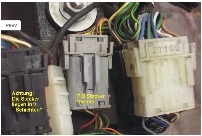
FID PINs

FID.jpgPINs of the FID:
PIN1 goes to PIN4 of the gear switch
PIN2 goes to PIN3 of the gear switch
PIN3 goes to PIN2 of the gear switch
PIN4 goes to PIN4 of the gear switch and ground
PIN5 is 12 Volt via F3 (permanent plus)
PIN6 comes from the engine electronic relay (= 12V, turns on the display)
PIN7 is for the sensor of the engine oil temperature
PIN8 is for the fuel level sensor

Data from http://www.powerboxer.de/armaturen-instrumente/316-4v1-fid-testen
 
Back
Top