Navigation
Install the app
How to install the app on iOS
Follow along with the video below to see how to install our site as a web app on your home screen.
Note: This feature may not be available in some browsers.
More options
-
Welcome, Guest! We hope you enjoy the excellent technical knowledge, event information and discussions that the BMW MOA forum provides. Some forum content will be hidden from you if you remain logged out. If you want to view all content, please click the 'Log in' button above and enter your BMW MOA username and password. If you are not an MOA member, why not take the time to join the club, so you can enjoy posting on the forum, the BMW Owners News magazine, and all of the discounts and benefits the BMW MOA offers?
-
Beginning April 1st, and running through April 30th, there is a new 2024 BMW MOA Election discussion area within The Club section of the forum. Within this forum area is also a sticky post that provides the ground rules for participating in the Election forum area. Also, the candidates statements are provided. Please read before joining the conversation, because the rules are very specific to maintain civility.
The Election forum is here: Election Forum
You are using an out of date browser. It may not display this or other websites correctly.
You should upgrade or use an alternative browser.
You should upgrade or use an alternative browser.
KGT Spline Lube
- Thread starter Semper_Fi
- Start date
Semper_Fi
Honey Badger
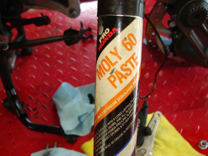
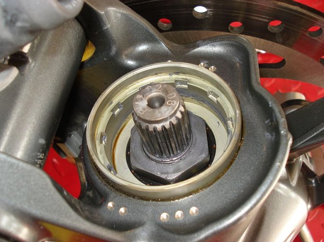
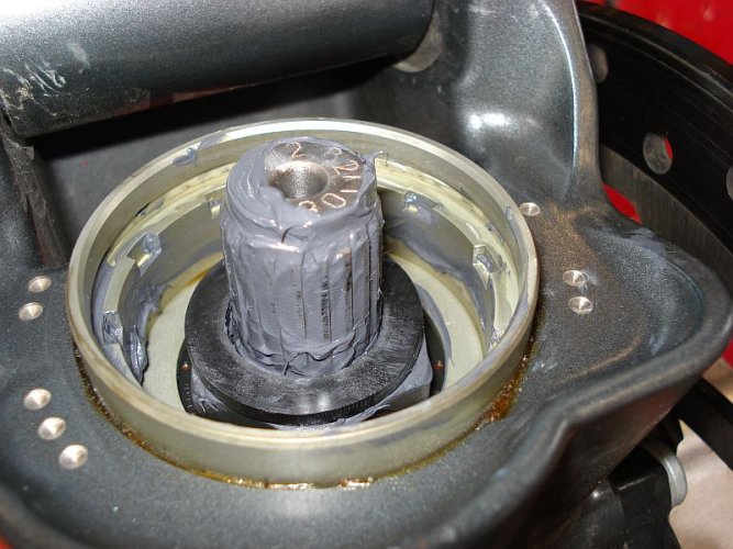
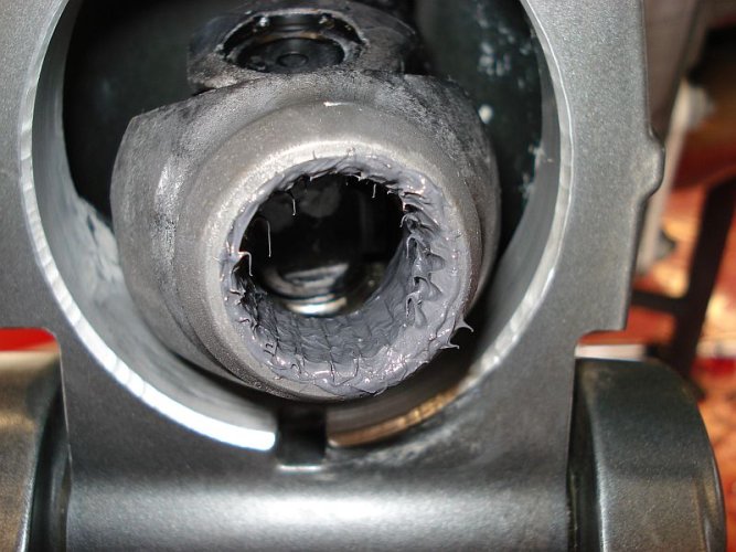
Apply the the moly paste onto the spline.
The best way to do it is by hand.
Please note this stuff is very messy and quickly gets everywhere - best thing to do is put on gloves, appliy liberally and wipe off any excess.
NOTE: after the spline was lubed I installed the flat washer, this ensures that you get the whole spline - then just drop the washer right on top.
Attachments
Last edited:
Semper_Fi
Honey Badger
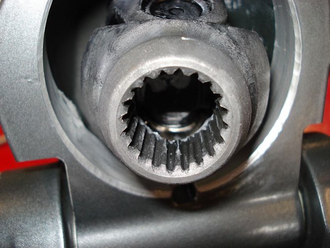
At this point with the spline and coupler lubed you can put it back together.
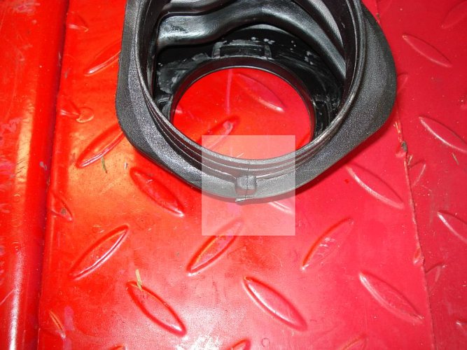
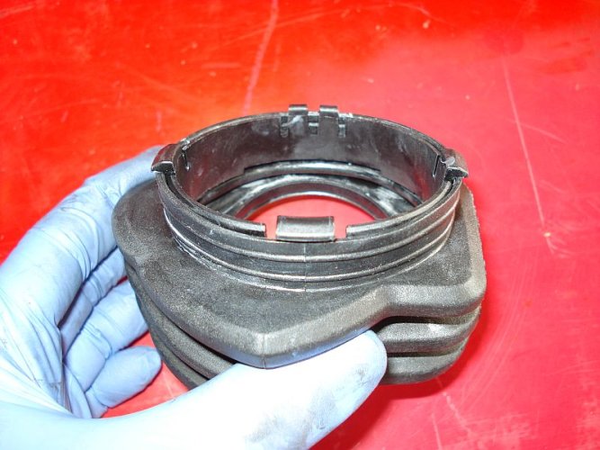
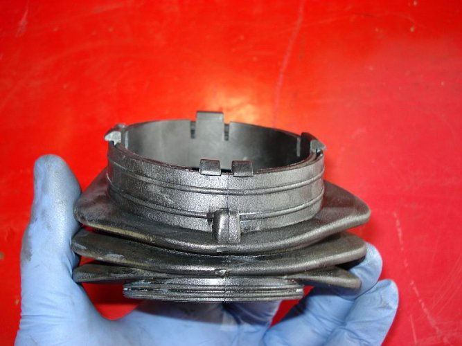
1 - you need to assemble the accordion boot
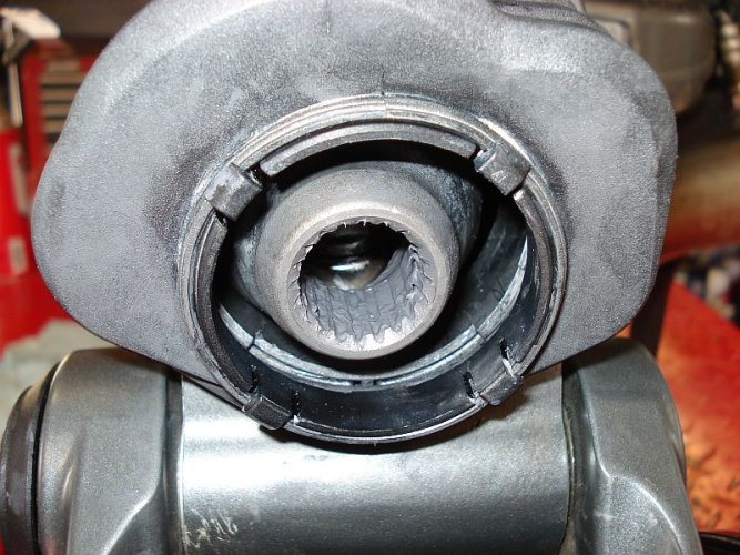
2 - you locate the accordion boot onto the driveshaft tube
3 - you line up the spline to the coupler and insert the spline into the coupler
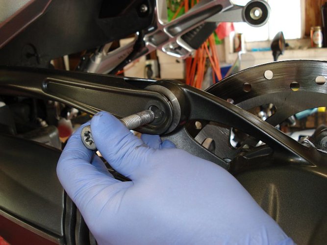
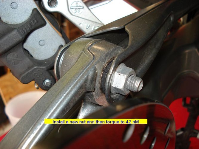
4 - connect driveshaft strut onto to rear drive housing and throw the driveshaft bolt in to support and free up your hands.
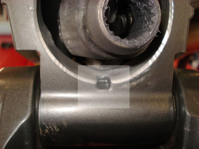
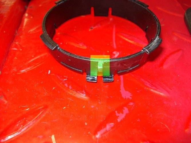
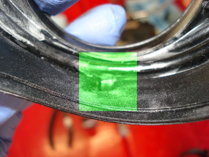
The highlighted area shows the notch feature which fits into the driveshaft tunnel receiving feature
************************************************************
Shown below is the "rear" portion of the accordion boot - meaning the portion of the accordion boot that is placed on the driveshaft tunnel
Attachments
Last edited:
Semper_Fi
Honey Badger
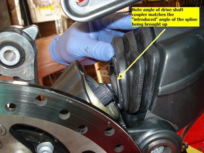
At this point we are ready to reconnect the rear drive to the driveshaft coupler.
Bring up the rear drive and try to line up the drive splines to the shaft coupler, as shown below.
Note the angle of approach.
Once there, push up
If it is not going in completely, move the disc slightly back and forth, until the alignment comes in and push up completely to mate the two parts.
Bring up the rear drive and try to line up the drive splines to the shaft coupler, as shown below.
Note the angle of approach.
Once there, push up
If it is not going in completely, move the disc slightly back and forth, until the alignment comes in and push up completely to mate the two parts.
Attachments
Last edited:
Semper_Fi
Honey Badger
Semper_Fi
Honey Badger
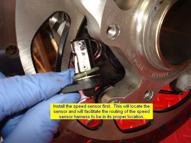
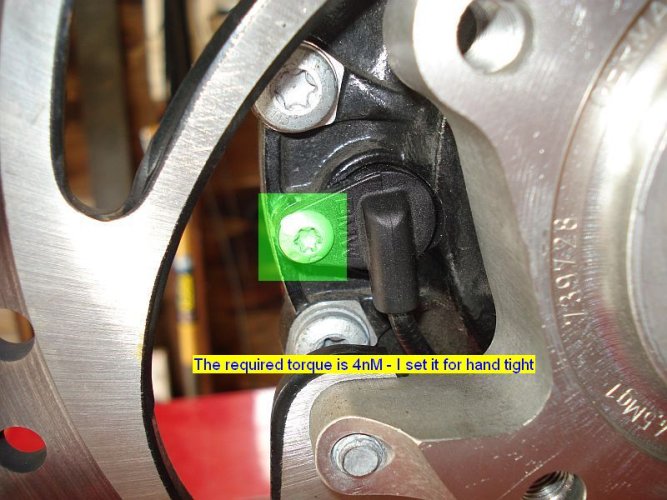
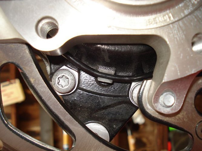
With the speed sensor correctly located run the speed sensor wire harness onto its mounting and attach points.
With the sensor in place, the proper routing and slack will fall into place. You will be able to tell that the routing is being done correctly as you install.
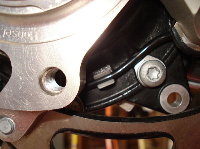
Working from the speed sensor to the front of the bike, insert the speed sensor harness into the reataining clip at the 7 o'clock position.
Ensure it is fully inserted as shown before proceeding.
Attachments
Last edited:
Similar threads
- Replies
- 43
- Views
- 13K
- Replies
- 15
- Views
- 3K
- Replies
- 29
- Views
- 13K
- Replies
- 9
- Views
- 8K
- Replies
- 0
- Views
- 281

