Navigation
Install the app
How to install the app on iOS
Follow along with the video below to see how to install our site as a web app on your home screen.
Note: This feature may not be available in some browsers.
More options
-
Welcome, Guest! We hope you enjoy the excellent technical knowledge, event information and discussions that the BMW MOA forum provides. Some forum content will be hidden from you if you remain logged out. If you want to view all content, please click the 'Log in' button above and enter your BMW MOA username and password. If you are not an MOA member, why not take the time to join the club, so you can enjoy posting on the forum, the BMW Owners News magazine, and all of the discounts and benefits the BMW MOA offers?
-
Beginning April 1st, and running through April 30th, there is a new 2024 BMW MOA Election discussion area within The Club section of the forum. Within this forum area is also a sticky post that provides the ground rules for participating in the Election forum area. Also, the candidates statements are provided. Please read before joining the conversation, because the rules are very specific to maintain civility.
The Election forum is here: Election Forum
You are using an out of date browser. It may not display this or other websites correctly.
You should upgrade or use an alternative browser.
You should upgrade or use an alternative browser.
Gerbing Permanent Controller Install DIY
- Thread starter Semper_Fi
- Start date
Semper_Fi
Honey Badger
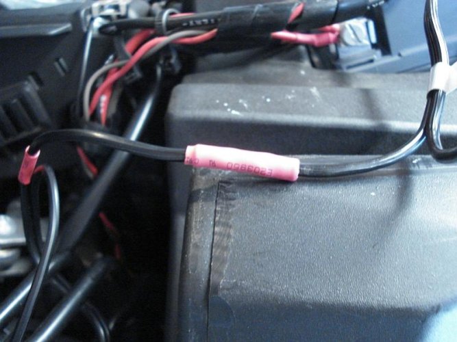
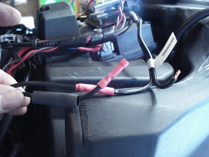
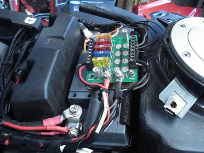
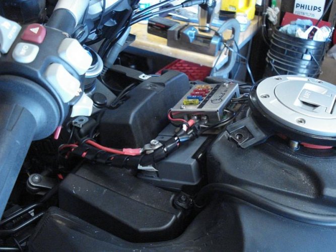
The more you add to your fuse panel, the messier it gets.
It is good practice to clean it up at the time of any new farkle install.
Here the grounds and power are organized.
On the left hand side (towards headlight) is the positive side, towards the gas tank are the negative (ground) sides. This is totally dependent on the type of fuse panel you have and where/how you located it.
Attachments
Last edited:
Semper_Fi
Honey Badger
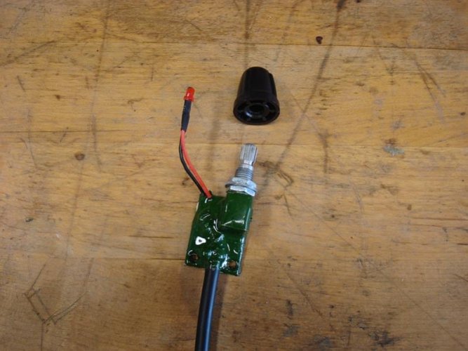
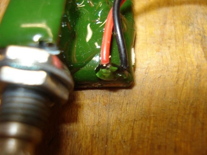
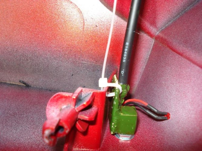
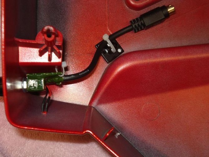
As the wires on the LED were moved around I noted that there was a small gap of the wire to the conformal coating on the Printed Circuit Board (PCB).
To ensure weather protection I dropped a little bit of super glue to seal the openings.
To ensure weather protection I dropped a little bit of super glue to seal the openings.
Attachments
Last edited:
Semper_Fi
Honey Badger
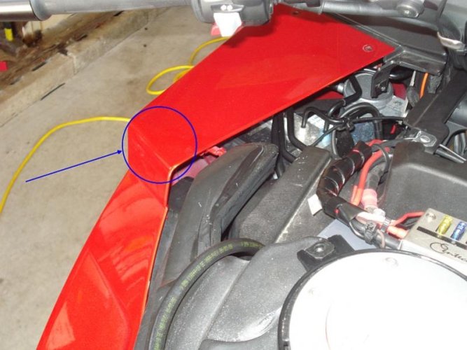
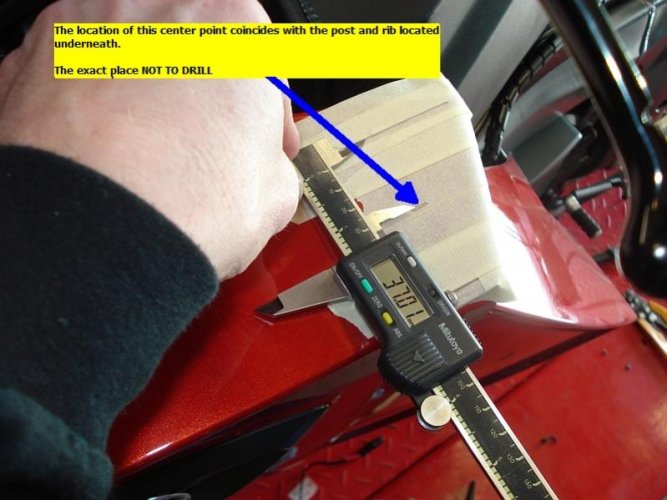
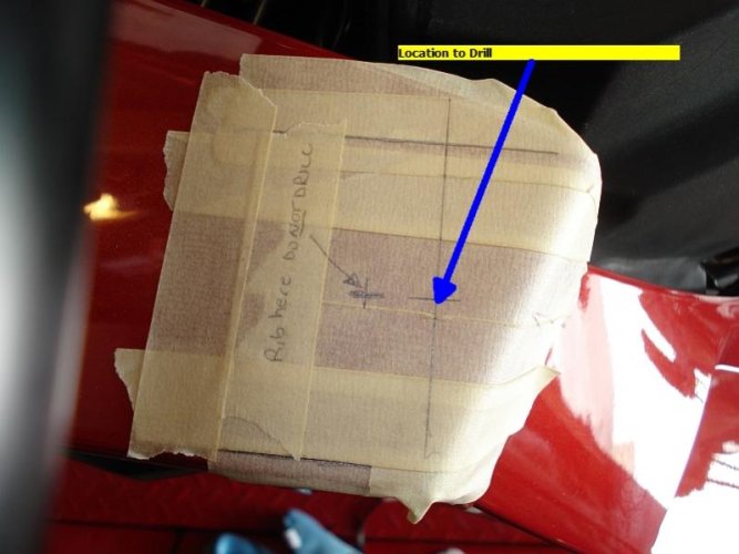
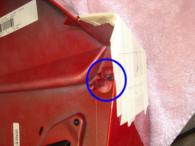
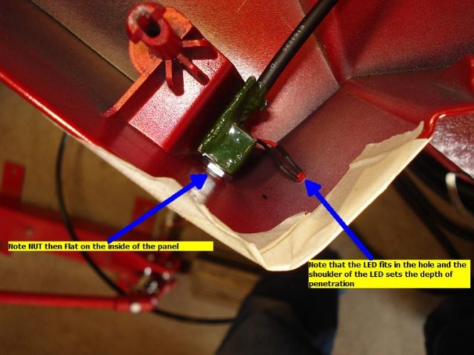
In the location of where I wanted to put the controller adjuster I encountered an issue that the mounting pin of the panel was directly below the hole to be drilled.
To address that the pin location was identified and a new location hole was selected.
To address that the pin location was identified and a new location hole was selected.
Attachments
Last edited:
Semper_Fi
Honey Badger
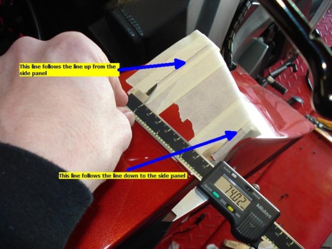
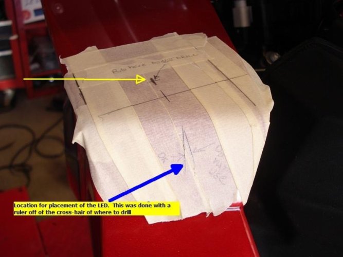
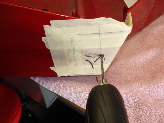
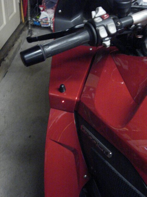
There is no science to the next part - to align the hole drilling for the LED, I used a straight edge and I aligned it with the + cross-hair (yellow arrow) of where to drill the shaft hole and then drew the line.
Then I got on the bike to see if it was lined up - it wasn't - so I drew the corrected one you see below and proceeded to drill the hole.
Then I got on the bike to see if it was lined up - it wasn't - so I drew the corrected one you see below and proceeded to drill the hole.
Attachments
Last edited:
Semper_Fi
Honey Badger
Semper_Fi
Honey Badger
Note - the Side Panel goes for about $780.00 be sure you want to do this.
After you start drilling there is no going back.
Some tips for drilling:
After you start drilling there is no going back.
Some tips for drilling:
- the instructions call out the sizes you need (9/32" for the shaft and 7/64" for the LED) or in metric-speak 7.25mm/2.77mm respectively
- Don't start with those - start with smaller pilot holes and work your way up.
- Use an electric drill as you have more control on speed (at least I do on mine)
- Drill from the finished paint side - this will leave a cleaner hole and minize paint flacking by the outer edges of the drill point
- Slow speed, even pressure - if you have sharp bits it will go quick
- try to have a drill size that is one level below what is stated in the instructions - you will then be able to gauge how much drill opening you have left.
- Last but not least - go slow, evenly and take your time
Attachments
Last edited:
Semper_Fi
Honey Badger
Similar threads
- Replies
- 43
- Views
- 13K
- Replies
- 15
- Views
- 3K
- Replies
- 29
- Views
- 13K
- Replies
- 9
- Views
- 8K
- Replies
- 0
- Views
- 282

