Navigation
Install the app
How to install the app on iOS
Follow along with the video below to see how to install our site as a web app on your home screen.
Note: This feature may not be available in some browsers.
More options
-

Welcome! You are currently logged out of the forum. Some forum content will be hidden from you if you remain logged out. If you want to view all content, please LOG IN!If you are not an MOA member, why not take the time to join the club, so you can enjoy posting on the forum, the BMW Owners News magazine, and all of the benefits of membership? If you click here, you have the opportunity to take us for a test ride at our expense. Enter the code 'FORUM25' in the activation code box to try the first year of the MOA on us!
You are using an out of date browser. It may not display this or other websites correctly.
You should upgrade or use an alternative browser.
You should upgrade or use an alternative browser.
Bing 32 (11/12) question
- Thread starter sprouty115
- Start date
sprouty115
New member
Sorry for not being clearer with the correct part names.
Here is what I did:
- full cleaning of the carbs but I did not take the butterfly screws out. I recognized those were swaged from previous rebuilds of Mikuni carbs. I did inspect to see it they were installed correctly.
- after the carbs were reinstalled I set the idle speed screw to just pinch a piece of paper.
- then I set the idle mixture screws 1 full turn out.
- had it running and made a few small adjustments of the idle mixture screws and the idle speed screws. It was better but clearly not running smoothly.
- so I asked about the choke set up and adjusted them per the recommendations above. They were definitely set wrong by the P.O..
- today was the first time I started the bike after the choke adjustment.
- I readjusted the idle mixture screws back to 1-turn out and the idle speed screws with a piece of paper + 1 turn in to make it idle.
After it was warmed up from a 20min ride, I started adjusting the idle mixture screws in small increments to balance the carbs and that's when I realized the left carb wouldn't drop rpm even all the way in.
So...tomorrow I will recheck points gap, timing and valve clearance. And if anything is off I'll correct it. I'll also pull the bowls and weigh the floats.
Not sure if this matters but when I first was checking the fuel level the reading I got from both bowls around 16mm. And in order to get it to 24mm I had to bend the float tang slightly past level, where before it was maybe 20 degrees in the other direction - it took a lot of bending to get the fuel level correct.
And thanks for sticking with me...
sprouty115
New member
One more quick question - since I'll be looking at the valves again, should I reset the intake to .15mm? Currently it's set to .10mm, which I thought was the factory spec, but from what I'm reading it seems like a lot of recommendations for .15mm.
The factory spec actually changed over time...it was 0.10 and 0.15mm at different points. Don't know if there's any consensus, but I would think that 0.15mm is better. The amount of heat subjected to the intake valve is less than the exhaust valve because inrush of fuel/air tends to cool the valve and seat. That said, it does get hot so having a wider setting might be better. It won't make any substantial difference in the way the bike runs. I suppose that with the clearance being bigger, the intake valve opens sooner and those a bit more fuel/air gets pushed into the combustion chamber. On the exhaust stroke, it will stay open a tad longer and more combustion products will get pushed out. But the differences are hardly noticeable.
sprouty115
New member
So two steps forward, one step back...
- I replaced both float needles and floats and set them to be parallel with the carb body when they just start flowing gas when lowered. This gave me a fuel level of about 22mm. FWIW, the old floats weighed 13 grams, the new ones weighed 12 grams.
- pulled both enrichers off the carbs and verified that the parts were assembled correctly - they matched the pics on the Airheads website, so all good there.
- took the bike for a warm up ride and then spent some time trying to sync the carbs. The left carb will now slghtly drop the rpm when I turn the idle mixture screw all the way in. However, the smoothest balance was with it turned out 1/4 from fully seated. Doesn't seem quite right, but the bike does idle at 1000rpm and is "reasonably" smooth at higher rpm.
So I moved on to re-checking points and timing.
- points were at .4mm, so got out my DMM to check the static timing and here is were I'm confused. I assumed I was looking for a transition from closed to open somewhere close to when the "S" appears in the timing window.
But with "S" set to the notch in the timing window no matter where I rotate the points carrier plate there is no change of state, the points simply stay open. In fact I need to rotate the engine 1/4 to 1/2 a revolution before I get to a point where phasing the carrier plate adjustment shows a changes of state.
Maybe I'm confused?
Engine rotated to "S" position.
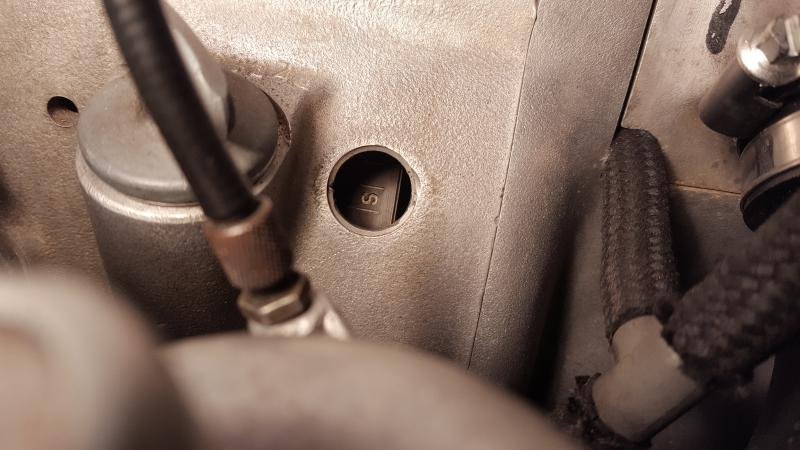
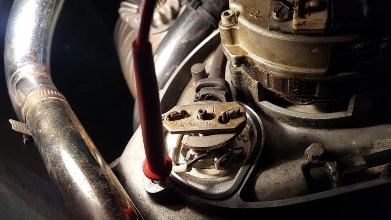
Points cam position with engine at "S" position - phasing points carrier plate makes no difference...
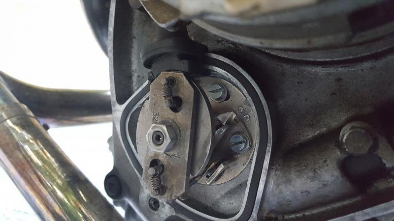
Points cam position with the engine rotated to a location where phasing the points carrier plate transitions the point from open to closed:
- I replaced both float needles and floats and set them to be parallel with the carb body when they just start flowing gas when lowered. This gave me a fuel level of about 22mm. FWIW, the old floats weighed 13 grams, the new ones weighed 12 grams.
- pulled both enrichers off the carbs and verified that the parts were assembled correctly - they matched the pics on the Airheads website, so all good there.
- took the bike for a warm up ride and then spent some time trying to sync the carbs. The left carb will now slghtly drop the rpm when I turn the idle mixture screw all the way in. However, the smoothest balance was with it turned out 1/4 from fully seated. Doesn't seem quite right, but the bike does idle at 1000rpm and is "reasonably" smooth at higher rpm.
So I moved on to re-checking points and timing.
- points were at .4mm, so got out my DMM to check the static timing and here is were I'm confused. I assumed I was looking for a transition from closed to open somewhere close to when the "S" appears in the timing window.
But with "S" set to the notch in the timing window no matter where I rotate the points carrier plate there is no change of state, the points simply stay open. In fact I need to rotate the engine 1/4 to 1/2 a revolution before I get to a point where phasing the carrier plate adjustment shows a changes of state.
Maybe I'm confused?
Engine rotated to "S" position.

Points cam position with engine at "S" position - phasing points carrier plate makes no difference...

Points cam position with the engine rotated to a location where phasing the points carrier plate transitions the point from open to closed:

Yes, the points should open when the S-mark is in the window. Remember you have two adjustments for points timing - the gap and the rotation of the points backing plate. And the 0.4mm (or 0.016") points gap is not mandatory. The gap can be vary on either side of that and the engine will be just fine with that. The points are "working" when closed allowing current to flow to the coils to saturate the windings. When they open, the field collapses and the spark happens. On a 2-cylinder system, the points will be closed plenty long with a gap from say 0.012 to 0.022". And also, a small points gap change makes a big difference in where the S-mark falls.
Be sure you're setting the gap with the points rubbing block on the high point of the points cam. Then try changing the gap to see how that affects where the S-mark is when the points open. Don't fall into the trap of elongating the slots in the points backing plate...absolutely not necessary...just change the points gap.
Be sure you're setting the gap with the points rubbing block on the high point of the points cam. Then try changing the gap to see how that affects where the S-mark is when the points open. Don't fall into the trap of elongating the slots in the points backing plate...absolutely not necessary...just change the points gap.
sprouty115
New member
Ok, that's what I thought was correct - that I should be looking for the transition from closed to open at the "S" mark.
(Btw, thanks for confirming how the system works, because it's been two years since my last rebuild and laying on my back last night in the dark trying to sort this out was making me doubt myself)
As to your other comments:
- I'm certain I adjusted the gap while I was on the high point of the points cam lobe. The first time I did it was with the advance mechanism/cam lobe installed. The second time (last night) I used the points tool that everyone seems use and the gap was the same.
- I'll pull it apart again as soon as I get a free minute and adjust the gap per your recommendation and see what happens to the "S" mark as I vary the gap.
One more question, if you don't mind - More searching last night uncovered the Chinese points with the long rubbing block. I assume when I get things apart if I discover they are installed I should replace them before I do anything else?
The points setting tool is very handy. However, it doesn't allow you to set to a gap bigger or smaller than that. Once must actually find the high point on the cam and then make manual adjustments.
Yes, if you have the Chinese points, you might as well stop until you get a replacement. As has been shown, the rubbing block is way too big and the gap can't be set. I suppose if there was a way to precisely shave off the offending part of the rubbing block, it could be reused. But that's likely difficult to do...easier just to install correct points.
Yes, if you have the Chinese points, you might as well stop until you get a replacement. As has been shown, the rubbing block is way too big and the gap can't be set. I suppose if there was a way to precisely shave off the offending part of the rubbing block, it could be reused. But that's likely difficult to do...easier just to install correct points.
sprouty115
New member
Ok, first I'll sort out what I have for points then focus on the gap.
Not sure I understand why I couldn't use the points tool to vary the gap, though? All it does is simulate the high point on the cam lobe, but without the advance mechanism in the way. Unless you mean I'd just need a different feeler gage (which I have)?
Not sure I understand why I couldn't use the points tool to vary the gap, though? All it does is simulate the high point on the cam lobe, but without the advance mechanism in the way. Unless you mean I'd just need a different feeler gage (which I have)?
The points setting tool is very handy. However, it doesn't allow you to set to a gap bigger or smaller than that. Once must actually find the high point on the cam and then make manual adjustments.
Yes, if you have the Chinese points, you might as well stop until you get a replacement. As has been shown, the rubbing block is way too big and the gap can't be set. I suppose if there was a way to precisely shave off the offending part of the rubbing block, it could be reused. But that's likely difficult to do...easier just to install correct points.
Kurt, I almost always agree with you, but I want you to re-think the first part of your response. The point setting tool (sleeve) simply gives the user the equivalent of the high point of the cam without the obstruction of the advance mechanism. A person should be able to set the point gap at any value, using a feeler gauge set with graduated leaves like the kind we might use to set valve clearance. A narrower than specified gap will cause the spark to occur sooner as the shoulder of the cam rotates clockwise to then contact the following block and kick the points open. The China made points with the oversized following block would blow the setting out of the water as you correctly noted.
sprouty115
New member
Thanks again guys, I'll report back as soon it stops raining and I get things back apart - unfortunately this is "yard project" until I free up shed space (my Triumph Thruxton is regrettably, being sold to make room).
sprouty115
New member
I appear to be stuck on the timing. Here is where I'm at -
new points and condenser from Max BMW. They don't seem to be the problematic type with the long can block, but I can't seem to get the static timing anywhere close. I've tried adjusting the gap from .004" to .020". I've also rotated the points plate to the extremes of the slots. And no matter what I do the transition from closed to open is probably 20 to 30 degrees before I see the "S" in the timing hole.
Pics may help...
With the "S" visible in the timing window the pink dot on the mechanical advance is in the position shown (use the red dot on the case as a reference point):
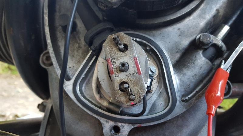
But here is where the closed to open transition occurs with the gap all the way down to .004" and the points plate rotated fully CW:
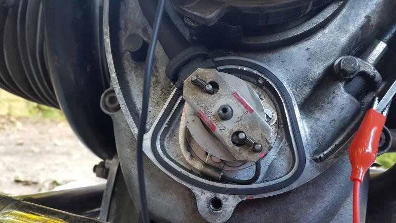
And it only gets worse with a larger gap and the points plate rotated CCW. There isn't even enough room to open the slots in the points plate to correct it. What am I missing?
new points and condenser from Max BMW. They don't seem to be the problematic type with the long can block, but I can't seem to get the static timing anywhere close. I've tried adjusting the gap from .004" to .020". I've also rotated the points plate to the extremes of the slots. And no matter what I do the transition from closed to open is probably 20 to 30 degrees before I see the "S" in the timing hole.
Pics may help...
With the "S" visible in the timing window the pink dot on the mechanical advance is in the position shown (use the red dot on the case as a reference point):

But here is where the closed to open transition occurs with the gap all the way down to .004" and the points plate rotated fully CW:

And it only gets worse with a larger gap and the points plate rotated CCW. There isn't even enough room to open the slots in the points plate to correct it. What am I missing?
sprouty115
New member
The point gap is set with the points rubbing block riding on the highest part of the advance cam. There is a tool available from Cycleworks that replaces the advance unit which allows for setting the gap without having to work around the arms of the advance unit.
It does look like your points are not the offending one. Here's something that compares the two side by side:
https://forums.bmwmoa.org/showthread.php?69216-78-R100-7-points&p=885249&viewfull=1#post885249
It does look like your points are not the offending one. Here's something that compares the two side by side:
https://forums.bmwmoa.org/showthread.php?69216-78-R100-7-points&p=885249&viewfull=1#post885249
sprouty115
New member
The point gap is set with the points rubbing block riding on the highest part of the advance cam. There is a tool available from Cycleworks that replaces the advance unit which allows for setting the gap without having to work around the arms of the advance unit.
It does look like your points are not the offending one. Here's something that compares the two side by side:
https://forums.bmwmoa.org/showthread.php?69216-78-R100-7-points&p=885249&viewfull=1#post885249
Thanks, I have the points setting tool and that's what I've been using to set the gap. And looking at that image in the link, I definitely have points with a shorter rubbing block.
sprouty115
New member
So after a bit more research and some helpful suggestions I've traced the problem to the flywheel - it was reassembled by someone one bolt hole off from the correct orientation.
I'm in the process of correcting that and then I should be good to go. Thanks again for all the help.
I'm in the process of correcting that and then I should be good to go. Thanks again for all the help.
sprouty -
I've heard of that possibility, but it would be way down the list of things. I presume you determined where TDC is by rotating the engine while looking into the spark plug hole or putting a soda straw in there. When the straw comes all the way out and then goes back down, the middle point between those two would be TDC. If the TDC mark is not in the window, that would be a problem. Somewhere there are measurements along the flywheel circumference that convert degrees to inches of circumference distance. It would be possible to make new temporary marks for TDC and the S-mark...the F-mark would be a bit more problematic.
I've heard of that possibility, but it would be way down the list of things. I presume you determined where TDC is by rotating the engine while looking into the spark plug hole or putting a soda straw in there. When the straw comes all the way out and then goes back down, the middle point between those two would be TDC. If the TDC mark is not in the window, that would be a problem. Somewhere there are measurements along the flywheel circumference that convert degrees to inches of circumference distance. It would be possible to make new temporary marks for TDC and the S-mark...the F-mark would be a bit more problematic.
sprouty115
New member
Yes, I confirmed it just as you described. Then I counted the number of flywheel teeth to "OT", it was about 18 and a half. So 18.5/93 = X/360, X = 72 (approx). This is the same as shifting the flywheel 1 bolt hole in a 5-bolt pattern 5/360 = 72.
I thought about remarking the flywheel but, I decided against that and started the disassembly process.
I know I have to start with the engine at TDC
I have to block the crank to keep it from pushing forward
I have to block the flywheel to keep it from rotating
I understand how to release the pressure on the spring diaphragm with the bolts and lock nuts
Right now I'm waiting to get back to work so I can modify my 27mm socket to fit into the swingarm. I'm going slow and keeping things organized.
Similar threads
- Replies
- 13
- Views
- 1K


