• Welcome, Guest! We hope you enjoy the excellent technical knowledge, event information and discussions that the BMW MOA forum provides. Some forum content will be hidden from you if you remain logged out. If you want to view all content, please click the 'Log in' button above and enter your BMW MOA username and password.

    If you are not an MOA member, why not take the time to join the club, so you can enjoy posting on the forum, the BMW Owners News magazine, and all of the discounts and benefits the BMW MOA offers?

Auxilliary Light Install KGT

Semper_Fi

Honey Badger
The articles, posts and comments in this tech section are posted by individual members and reflect their personal thoughts and experiences with repairing, maintaining, and generally working on motorcycles. This information may require specific knowledge and skills, may or may not be correct or current to model.

The authors of information found here and the BMW MOA take no responsibility for ensuring the accuracy of any information (including procedures, techniques, parts numbers, torque values, tool usage, etc.), or further for any damage of any kind or injuries incurred or caused by anyone following the instructions or information found here.

It is the duty of the individual to either assume the liability himself for responsibly using the information found here, or to take the bike or accessory to a Dealer or other qualified professional service.


Lastly, please ensure you dispose of your used chemicals, oils and fuels in an environmentally responsible manner. Most Auto Parts stores and service stations will accept used oil and lubricants, tires and batteries, please check for your local availability.

This article, text and photos are Copyright of the individual authors and the BMW MOA, any copying or redistributing is permitted only by prior written authorization.
 
The following DIY project will show how to install a set of auxilliary lights on a KGT, specifically a 2009 KGT 1300.

NOTE - please check your local laws to understand the requirements associated with Auxilliary lighting.

For example, in Massachusetts, it is a state law requirement that if the auxilliary lights are on, they are automatically turned off when the Hi-Beam on the main headlight system is activated.

Instructions for shutting off the auxilliary lights when the high-beam is turned on are included in the DIY
 
Last edited:
PROJECT OVERVIEW

The premise of this DIY is that I wanted to have auxillary lights on the bike mounted under the oil cooler area as in the RT, and I did not want to mount them on the caliper as others have. After some searching and vendor calls I realized they do not make mounts for under the cowl for the newer KGT.

However I was provided a link for Jimmy Mounts from BMW Denver. These mounts are made specifically for the PIAA* Style lights so I ordered them. They mount under the rear view mirrors. I checked them out and they looked pretty good (to me) so they were ordered.

* although made for the PIAA light it appears they will accept any vertically mounted style light

Here is the link

The project consists of 3 to 4 seperate steps.

Step one - prepping and mounting the Jimmy mounts

Step two - mount the lights to the Jimmy mounts

Step three - lay out and install the wiring harness**

Step four - modify wiring to support High Beam shut off of aux lights - check your local law requirements


** Please note that using the Jimmy mounts and the amount of excess wiring provided in the harness you WILL have to cut the harness and connectors in various places - this will obviously void any warranty provided by PIAA so please be fully cogninzant of this aspect of the install if you plan to do it.
 
Last edited:
Install Hardware 1

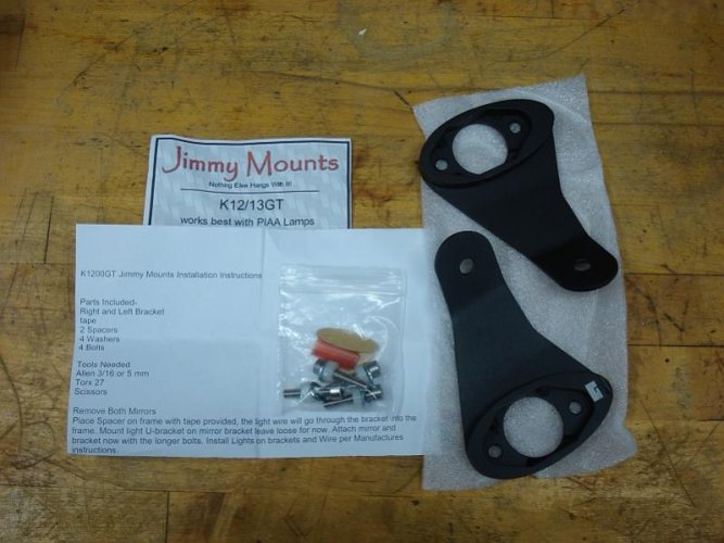
Shown below are the Jimmy mounts, their hardware and instruction sheet.

they are power coated black and are very robust - suitably able to support the PIAA Light
 

Attachments

  • 1 - jimmy mounts.jpg
    1 - jimmy mounts.jpg
    64.9 KB · Views: 452
Install Hardware 2

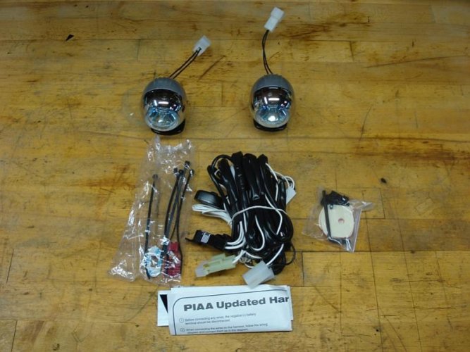
The lights and their accompanying parts
 

Attachments

  • 3 - piaa contents.jpg
    3 - piaa contents.jpg
    71.5 KB · Views: 452
Bike Prep

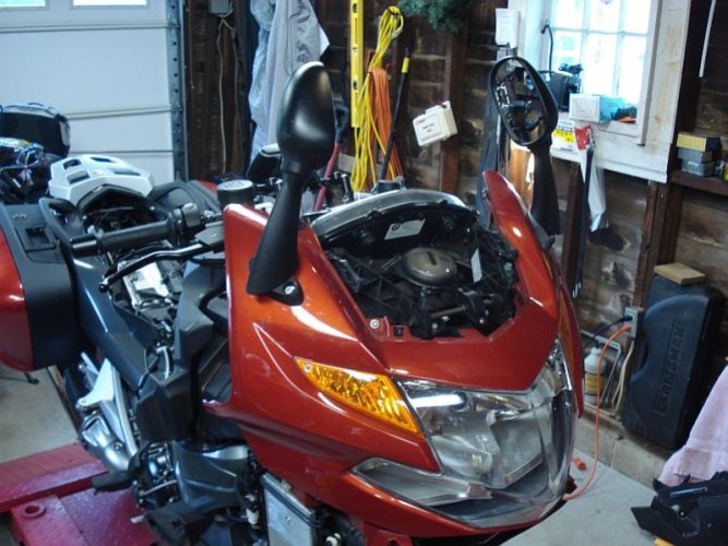
You need to get the bike to a usable access position to work on.

The easiest is removing all the plastic and windshield to be able to properly mount, route and install the various items.

This link shows how you how to remove all the plastic

This link shows how to remove the windshield - please note you can stop when you get to post # 15 on this one
 

Attachments

  • 4 - bike prep1.jpg
    4 - bike prep1.jpg
    81.5 KB · Views: 452
Last edited:
Jimmy Mount Preparation

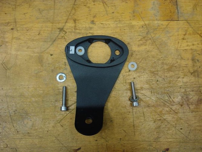
Shown here is the sequence of hardware that will be used to mount the Jimmy Mount to the bike.

From left, it will be a Hex screw, with a washer, the plastic sleeve slides on next and then that hole combination is put into the mounting hole and then the hex bolt is threaded onto the bike supporting the mount.

The hex bolt has a 5mm head.
 

Attachments

  • 5 - Jiimy mount prep.jpg
    5 - Jiimy mount prep.jpg
    74.3 KB · Views: 451
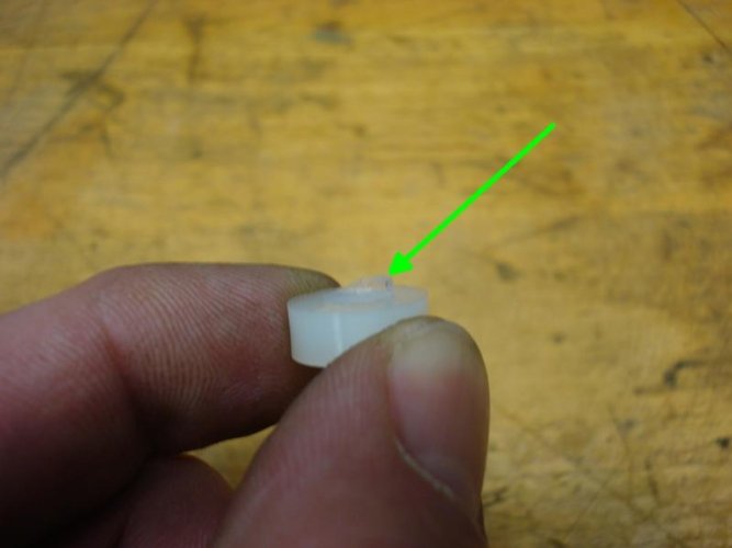
Things to note - the first

Check for flash on the plastic sleeve and remove it - this will provide a better fit
 

Attachments

  • 6 - flash on spacer.jpg
    6 - flash on spacer.jpg
    28.2 KB · Views: 443
Second

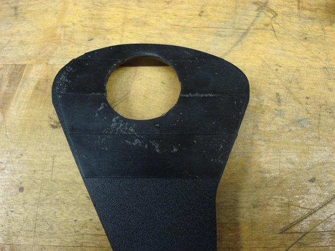
The bottom of the Jimmy Mount will flush mount to the side of the front cowl - even though I do not plan to remove the mounts I did not want to have the area damaged by the permanent contact, so I added some rubberized tape onto the mounting area to protect the painted surface that will be in contact here.

Optional - not required
 

Attachments

  • 7 - rubber backing.jpg
    7 - rubber backing.jpg
    66.5 KB · Views: 442
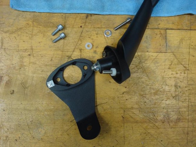
Shown is the mirror removed and how it would mate to the mount for install.

DO NOT INSTALL - because you need to mount the lights first and route the light harness thru the mount before putting the mirror(s) back onto the bike.
 

Attachments

  • 8 - how it would mount.jpg
    8 - how it would mount.jpg
    73.6 KB · Views: 449
Mounting the Lights

OK - the mount is preped and we are ready to install the light onto the mount.

The instructions call out that the small hole on the side of the mount is for the wire harness.

As you can see PIAA provides some nice connectors that in no way will fit thru the hole.

Here you have to choices:

1 - you can leave the connectors intact and wire the lights with the harness outside of the mount

2 - you can cut off the connectors and run the light wires thru the hole as provided.


I went with option 2 because I wanted a clean look - but be advised any modification to the harness will void your warranty for the PIAA product, and probably any product you use.
 

Attachments

  • 9 - wtf 1.jpg
    9 - wtf 1.jpg
    56.3 KB · Views: 445
Light Preparation

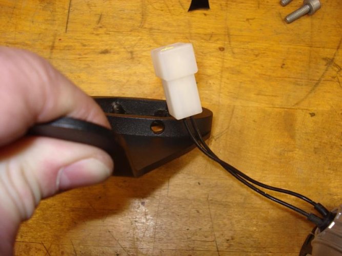
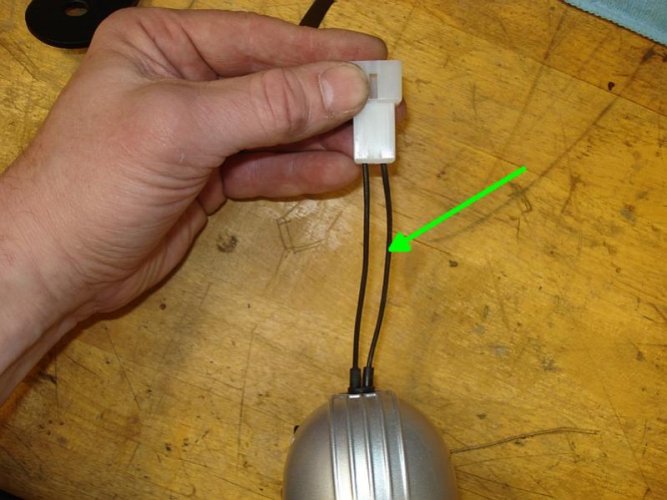
Since I am going to cut off the connector, I wanted to identify/maintain the same wire polarities to the lights.

I checked both connectors and if you pull them out straight you will note that one wire will be slightly longer (green arrow) because there was more slack, in my case, the longer wire in each connector is associated to the ground side of the wiring.

So the shorter wire is postive, the longer is negative and it was the same for the other light.
 

Attachments

  • 10 - longer on right - ground.jpg
    10 - longer on right - ground.jpg
    63.7 KB · Views: 448
Last edited:
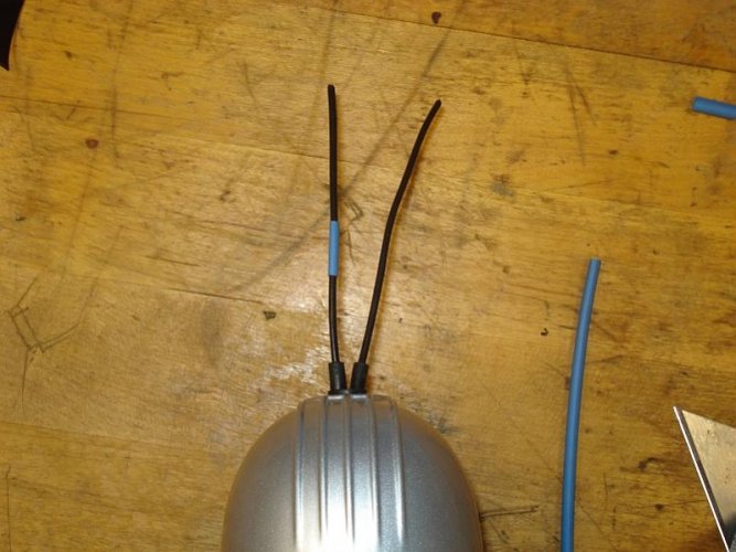
I put a small piece of shrink tubing to identify the postive line and then did the same for the other light.
 

Attachments

  • 11 - post id on left.jpg
    11 - post id on left.jpg
    68 KB · Views: 444
Mounting the lgihts to the mounts

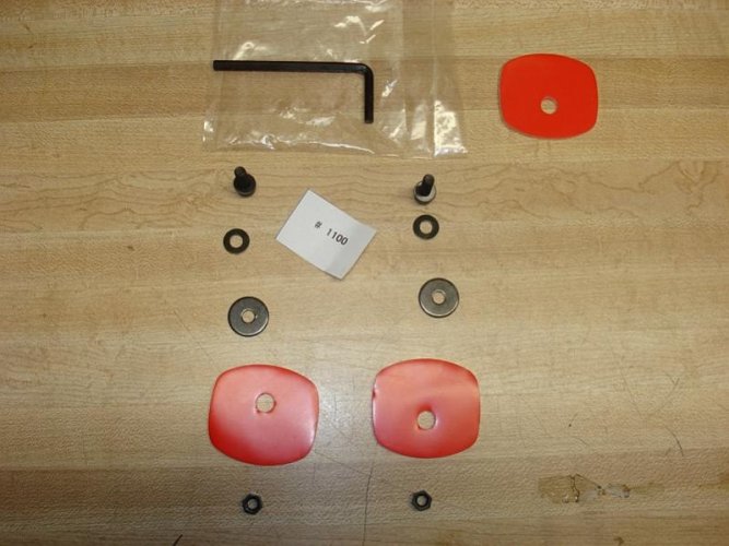
Displayed below is the assortment of hardware to mount the lights, depicted is the order of their assembly (Top to bottom)
 

Attachments

  • 12 - piaa mounting hardware.jpg
    12 - piaa mounting hardware.jpg
    67.3 KB · Views: 442
Last edited:
OPTIONAL STEP

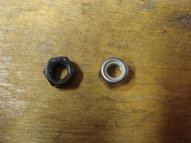
The hardware supplied came with a standard nut, I did not think that was robust enough and replaced it with an M4 Nylock style to ensure that it would not come loose.
 

Attachments

  • 18 - replacement hardware.jpg
    18 - replacement hardware.jpg
    66.5 KB · Views: 443
Last edited:
OPTIONAL

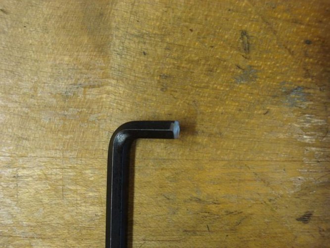
The supplied 4mm Allen is a standard allen, however I found it was a little too long to cleanly fit and tighten the screw heads so i took out about half the length and it fit fine.

When the light is installed the lower body portion will interfere if a standard allen wrench is used - hence the modification.
 

Attachments

  • 19 -  modified 4mm wrench.jpg
    19 - modified 4mm wrench.jpg
    72.5 KB · Views: 280
Last edited:
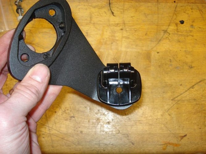
Shown is the general position of the PIAA mount in relation to the Jimmy Mount.

Please note that I have the adhesive mounted under the PIAA mount but I left the side that would touch the Jimmy Mount still covered so it would not adhere.
 

Attachments

  • 13 - mounting the piaa to the jimmy.jpg
    13 - mounting the piaa to the jimmy.jpg
    71.3 KB · Views: 280
Last edited:
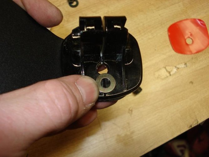
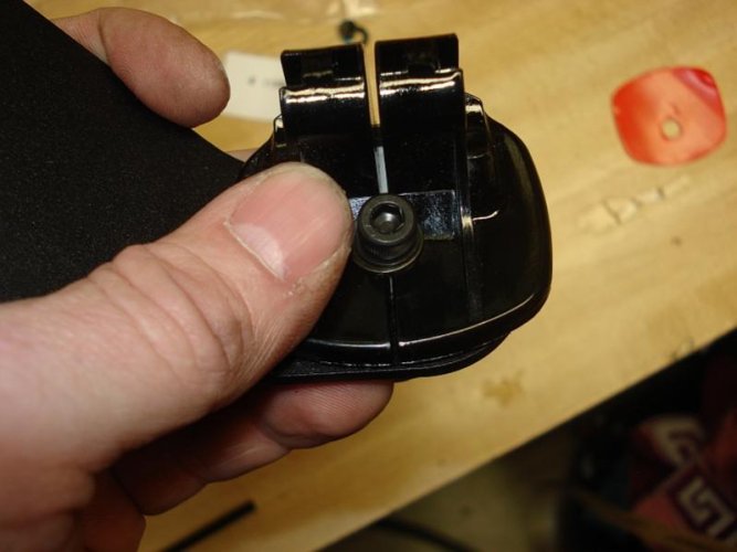
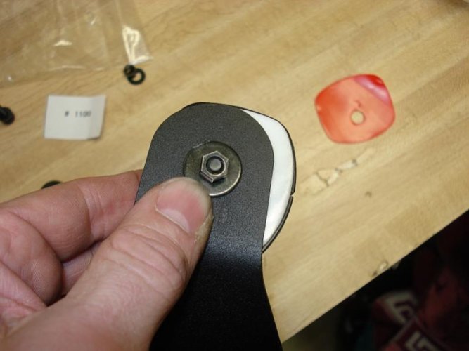
Larger washer and nut.

Please note the orginal hardware nut is shown - it was here I realized I did not like it and went to the hardware store to replace it with the Nylock style.
 

Attachments

  • 16 - mounting to the jimmy 4.jpg
    16 - mounting to the jimmy 4.jpg
    42.2 KB · Views: 280
Back
Top