Navigation
Install the app
How to install the app on iOS
Follow along with the video below to see how to install our site as a web app on your home screen.
Note: This feature may not be available in some browsers.
More options
-
Welcome, Guest! We hope you enjoy the excellent technical knowledge, event information and discussions that the BMW MOA forum provides. Some forum content will be hidden from you if you remain logged out. If you want to view all content, please click the 'Log in' button above and enter your BMW MOA username and password. If you are not an MOA member, why not take the time to join the club, so you can enjoy posting on the forum, the BMW Owners News magazine, and all of the discounts and benefits the BMW MOA offers?
You are using an out of date browser. It may not display this or other websites correctly.
You should upgrade or use an alternative browser.
You should upgrade or use an alternative browser.
Auxilliary Light Install KGT
- Thread starter Semper_Fi
- Start date
Semper_Fi
Honey Badger
Hi beam shut off
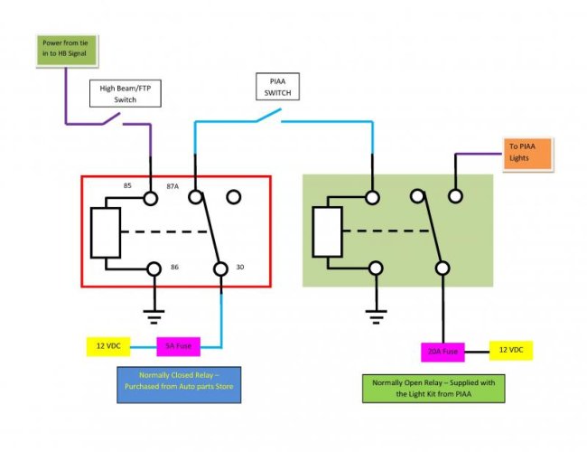
The schematic below shows how I control the Auxilliary lights via the Hi Beam Switch.
As stated earlier I routed all the voltage requirements thru my Centech panel.
If you do not have a fuse panel you can still wire as above except that you will need to add 5 amp fuse for the Normally Open relay - all details are next
Relay Function and Operation
The relay on the left is a NORMALLY CLOSED RELAY - meaning that when the relay is NOT ENERGIZED the contacts are in such a postion that there is continuity between points 87A (sometimes it is shown as 87O) and 30.
So that if you put voltage on pin 30 you will see that voltage on 87A - when the relay is activated the voltage that is on 30 is now disconnected from 87A/O and there is no voltage there.
By connecting the power that goes to the PIAA Switch thru the Normally Closed contacts of the relay you can control the PIAA Lights - when the high beam is off the coil is not turned on and the voltage signal reaches the PIAA switch and the PIAA lights can be turned on and off at the users discretion.
Now if the PIAA Lights are on and the high beam is activated there will be voltage on pin 85 of the Nortmally Closed relay and this activates the coil (becasue the other end of the coil is grounded).
When the coil is activated the Normally Closed Relay now switches from 87A to 87 - since 87 is intentionally not connected to anything the voltage signal going to the PIAA switch is now interrupted and the PIAA lights shut off.
WIRING OF THE RELAY
The control for this relay is obtained from the hot side of the High Beam wire (Pin 85). Ground is attached to Pin 86.
When the Hi Beam or Flash to Pass (FTP) trigger is engergized it activates the relay and the control signal to the PIAA Switch is interupted.
12 volts is obtained from either the fuse panel or relay, a 5A fuse is placed in line to this line and it is connected to pin 30 of the Normally open relay.
Connect the orginal white trigger wire from the PIAA switch to the Normally Close (Pin 87A/O) of the relay.
The other relay is the PIAA relay and it is shown for reference only.
Attachments
Last edited:
Semper_Fi
Honey Badger
Getting the Trigger Signal for the High Beam Cut Off
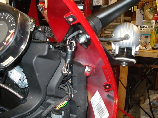
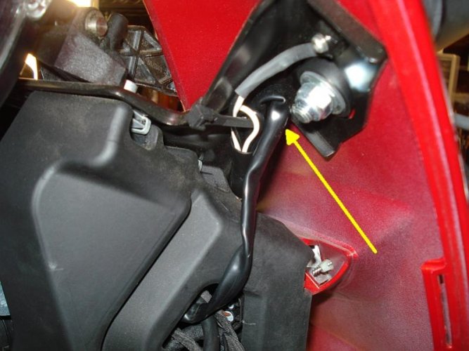
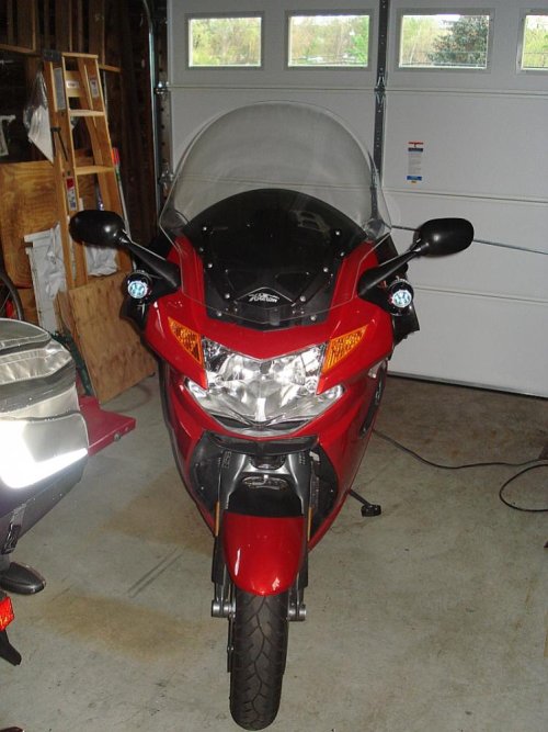
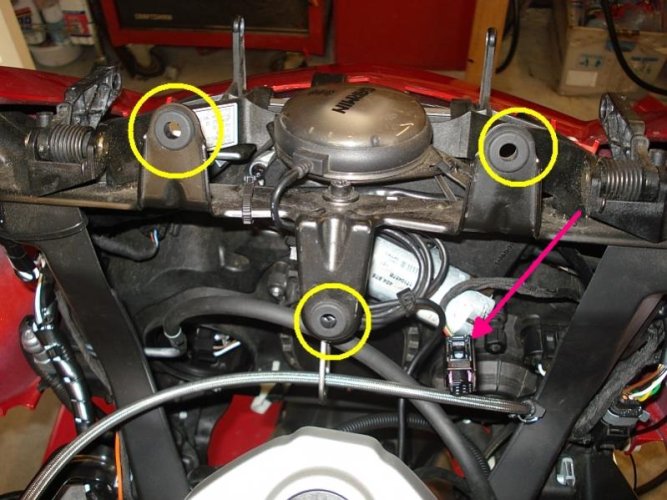
I did not even consider tearing into the headlight switch on the handlebar to pull the trigger signal, instead I went directly to the head light panel.
To gain better access and provide some room I removed the instrument panel.
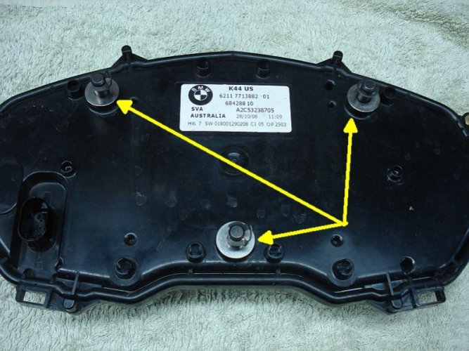
It is very easy - it has 3 mounting points and one connector
Shown below in the Yellow Circles are the connection points.
The Pink Arrow shows the IP connector
I did not even consider tearing into the headlight switch on the handlebar to pull the trigger signal, instead I went directly to the head light panel.
To gain better access and provide some room I removed the instrument panel.
It is very easy - it has 3 mounting points and one connector
Shown below in the Yellow Circles are the connection points.
The Pink Arrow shows the IP connector
Attachments
Last edited:
Semper_Fi
Honey Badger
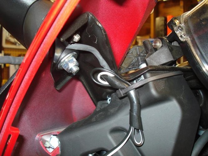
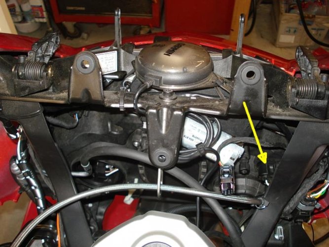
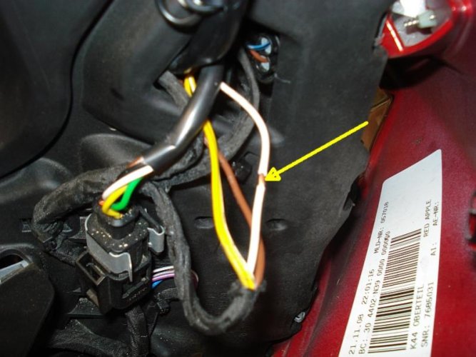
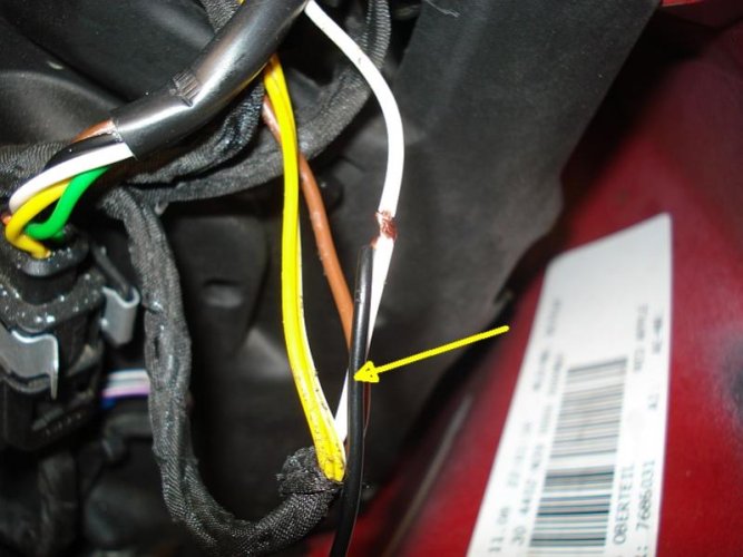
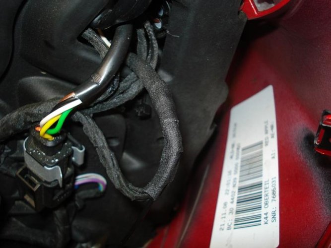
Shown below is how I got to the point to acquire a trigger signal - the steps are as follows:
Disconnect the Headlight Connector from the back of the housing.
Cut the supporting zip-tie and pull back the connector as far as you can.
NOTE 1 - I could not pull it all the way out.
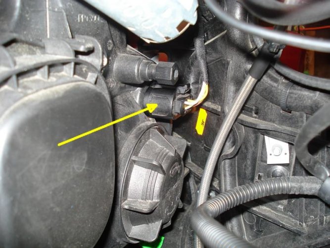
Cut back some of the cloth tape and access the WHITE WIRE
NOTE 2 - please verify the wire you are accessing if the bike you are working on is not a 2009 KGT 1300.
Open up the insulation of the white wire slightly so that you can attach a tie in trigger wire
Disconnect the Headlight Connector from the back of the housing.
Cut the supporting zip-tie and pull back the connector as far as you can.
NOTE 1 - I could not pull it all the way out.
Cut back some of the cloth tape and access the WHITE WIRE
NOTE 2 - please verify the wire you are accessing if the bike you are working on is not a 2009 KGT 1300.
Open up the insulation of the white wire slightly so that you can attach a tie in trigger wire
Attachments
Last edited:
Semper_Fi
Honey Badger
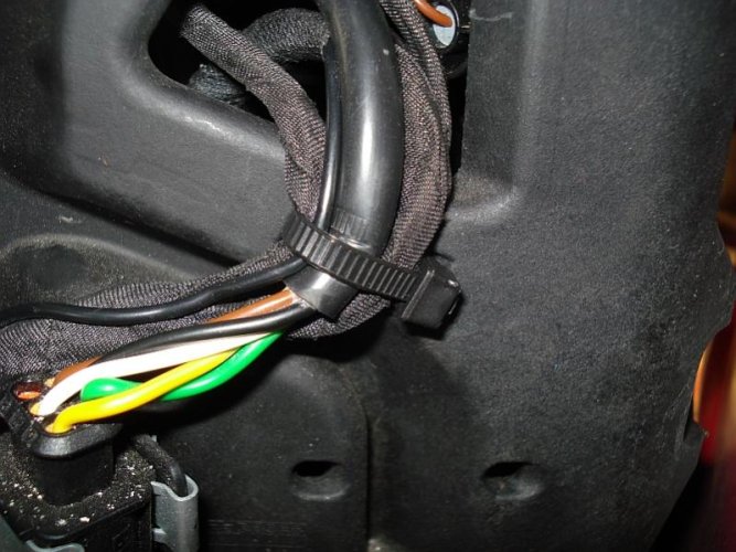
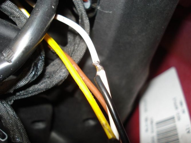
I attached a trigger wire and wrapped it around the exposed wire of the Hi Beam Line.
I used a black wire because I did not want to the trigger wire to stand out when dressed into the bike
I did not use a positap because I wanted a soldered connection - use what you want
I used a black wire because I did not want to the trigger wire to stand out when dressed into the bike
I did not use a positap because I wanted a soldered connection - use what you want
Attachments
Semper_Fi
Honey Badger
Semper_Fi
Honey Badger
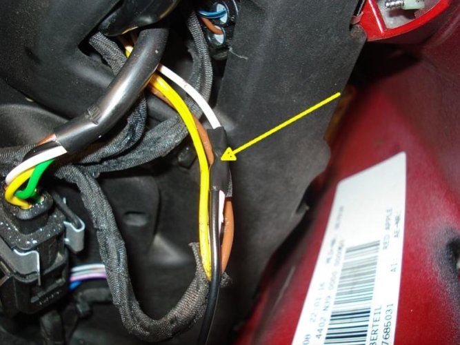
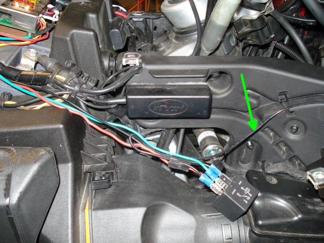
Replacing the cloth tape with new cloth tape to revert back to orginal condition.
The trigger is now accessed, you can connect the head-light connector back onto the housing and give yourself about 3 feet of trigger wire as slack.
This portion is complete, now onto the PIAA Switch trigger wiring
The trigger is now accessed, you can connect the head-light connector back onto the housing and give yourself about 3 feet of trigger wire as slack.
This portion is complete, now onto the PIAA Switch trigger wiring
Attachments
Last edited:
Semper_Fi
Honey Badger
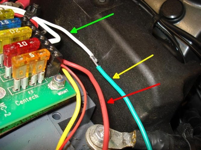
In the orginal PIAA Light install the trigger of the PIAA switch needs to go to 12 VDC - here we are going to tie it into a relay as explained earlier.
1 - Remove white wire of the PIAA Light Switch Trigger from Centech or battery - Green Arrow
2 - Create and attach a wire to solder to the white wire - Yellow Arrow - this will go to the relay
3 - attach a line to a fused 12 V source - on my Centech I selected a 5A fuse as this is a very low power signal - Red Arrow - this will go to the relay
Attachments
Last edited:
Semper_Fi
Honey Badger
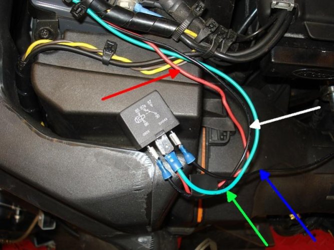
Shown here is the relay to control the PIAA light switch free-wired.
Red Arrow is the 12 volt fused source - going to Pin 30 of the relay
White Arrow is the Ground connection - from battery or negative of fuse panel - going to pin 86 of the relay
Blue Arrow is the trigger signal from the Headlight - going to Pin 85 of the relay
Green Arrow is the line that was attached to the white trigger wire from the PIAA switch going to Pin 87A of the relay.
Shop tip - great testing opportunity before final dressing.
Starting from the top:Red Arrow is the 12 volt fused source - going to Pin 30 of the relay
White Arrow is the Ground connection - from battery or negative of fuse panel - going to pin 86 of the relay
Blue Arrow is the trigger signal from the Headlight - going to Pin 85 of the relay
Green Arrow is the line that was attached to the white trigger wire from the PIAA switch going to Pin 87A of the relay.
Attachments
Last edited:
Similar threads
- Replies
- 43
- Views
- 13K
- Replies
- 15
- Views
- 3K
- Replies
- 0
- Views
- 339
- Replies
- 29
- Views
- 13K
- Replies
- 9
- Views
- 8K