b25bsaboy
New member
Good morning,
Put the battery into the 76 R 75/6 project and it lights up, somewhat! Horn works (surprise), sorted out the signal lights (they work), head light works. Started looking at the birds nest inside the head light bucket and decided to remove what I did a year ago at straighten out the wiring routing as it looked like a bad day on any freeway in the world in the middle of rush hour.
Took the trust tablet and started looking for some schematics that made sense and they are out there. This brings me to several questions that I need some enlightening.
1. Wiring usually is in two colours, as an example brown/yellow. But on any schematic that I have seen it only spells out brown. Why is that, as the British bike schematics list both colours to lessen the confusion.
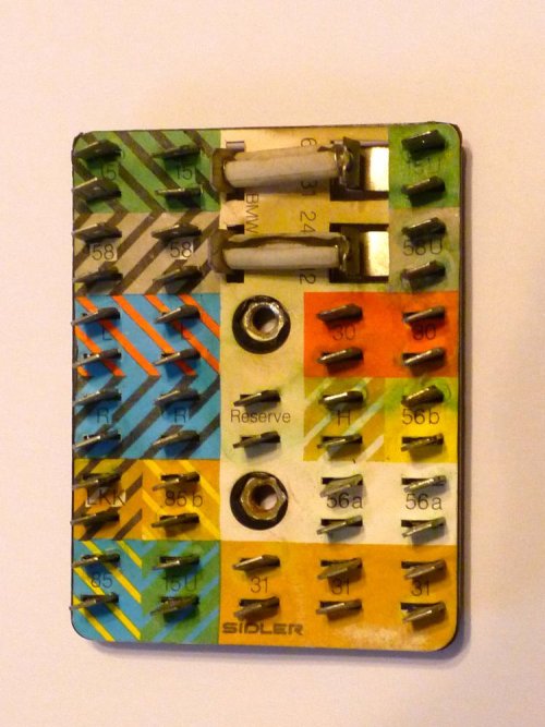
2. It appears that the connector board is different in who manufactured it. The board that I replaced has a slot brown/black called LKK. There is nothing that I have seen that has these markings. Another example is the green 15U at the top right hand corner. The drawings schematics list it as 15. Is there a reason for this?
3. The wiring harness itself seems to be somewhat the same. What I mean is that the 1975 BMW R60/s, R75/6, R90/6 & R90S are the same. Is this correct.
4. Was there a change up from the years 1975 to 1976 wiring harness. If so what are the differences.
I will tell you that the wiring harness setup with the connector board is much better than the British Bikes, especially the later Norton Commando's that had two wiring harnesses that came together under the full tank, and if not done correctly was bound to fail.
Put the battery into the 76 R 75/6 project and it lights up, somewhat! Horn works (surprise), sorted out the signal lights (they work), head light works. Started looking at the birds nest inside the head light bucket and decided to remove what I did a year ago at straighten out the wiring routing as it looked like a bad day on any freeway in the world in the middle of rush hour.
Took the trust tablet and started looking for some schematics that made sense and they are out there. This brings me to several questions that I need some enlightening.
1. Wiring usually is in two colours, as an example brown/yellow. But on any schematic that I have seen it only spells out brown. Why is that, as the British bike schematics list both colours to lessen the confusion.
2. It appears that the connector board is different in who manufactured it. The board that I replaced has a slot brown/black called LKK. There is nothing that I have seen that has these markings. Another example is the green 15U at the top right hand corner. The drawings schematics list it as 15. Is there a reason for this?

3. The wiring harness itself seems to be somewhat the same. What I mean is that the 1975 BMW R60/s, R75/6, R90/6 & R90S are the same. Is this correct.
4. Was there a change up from the years 1975 to 1976 wiring harness. If so what are the differences.
I will tell you that the wiring harness setup with the connector board is much better than the British Bikes, especially the later Norton Commando's that had two wiring harnesses that came together under the full tank, and if not done correctly was bound to fail.

