B
BMWeebsner
Guest
Hello all,
I am a new BMW owner and so far have loved the bike. However like many, I found the accessory ports wanting when connecting heated gear. I searched the web for answers but found the responses short for my needs. So for my first post, I would like to add my experience to help others who may do a similar web search. I wanted to add pictures in hope it will assist, but found I was limited to 1.
Suggested skills-Capable of soldering, comfortable with tools and removing componets on the bike.
Tools- T-30 and T25 Torx, wire strippers, 10MM box, #2 Phillips, Small flatblade screwdriver, Butane soldering gun, Digital Multi-Meter
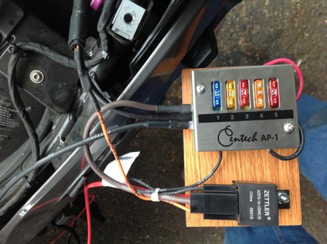
Parts - Centech AP-1, RP-170 relay with harness, 12 GA stranded Red and Black wire, Lock tight Blue, large and small zip wire ties, 1-1/4 x 3 industrial grade velcro patch (stickon type), 1pc screw with nut (I used a 6-32 x 3/4 as i had them), protective tape, shrink tubing to fit over a pair of 12 Ga wires or a single 12Ga wire, and one PC of wood large enough for the AP-1 and relay. (I used a wood floor sample).
I chose to install my fuse and relay unit on a board with velcro to allow access when needed under the seat near the computer. All connections and ends with terminals are soldered and shrink tubed. I verified which wire provided power for my trigger with a mutimeter, and tested the circuit along the way. These steps are not listed but I suggest them. I used the Harness that connects the Acc port to the bike harness to elliminate any OEM plug modifications.
1. Remove luggage and rear rack. This will require you to remove the back turn/tail lights as if you where changing a bulb.
2. Remove the required screws to get to and remove the short wire harness to the accessory port.
3. Cut wires of the harness near the halfway point between the 2 ends. 1 will be the wire harness side used for the triggerand 1 will be the acc port side connected to the AP-1.
4. Mount the AP-1 and relay on the board or what ever you chose.
5. Cut to length and wire the "load" wire from the relay to the Fuse board "+" terminal.
6 Connect the given 10 Ga Black wire to the AP-1 "-" terminal
7. Cut to length and connect the orange trigger from the relay to the positive lead that will connect to the wire harness of the bike on the proper connector from step 3. (used to power the ACC port).
8. Cut long 1 red and 1 black 12 GA wire, strip 1/8 of one end and properly connect to the AP-1. I routed the wires underneath the fuse box, and then added shrinktubing to keep them together. Make sure you align the proper fuse to power your needs. I chose 10A as that is the max rating of the ACC plug per my research.
9. Cut the 12GA wires to length and connect to the remaining connector from step 3 that goes to the acc port.
****of course you could now install additional 12 GA wires to power other items as well at this time. Just cut them long.(I chose 12G as it provides me up to 20Amp at the max distance I would need on the bike)
10. Apply the velcro (male/female) to the board, peel the remaining backing off the velcro and place the board with AP-1 and relay where you want it. Far enough back to be out of the way, but not sticking out where the tail light goes. Hold for a few moments to allow the tape to stick. I would suggest washing the mounting area first and allowing it to dry before applying.
11. Connect the ACC connector to the outlet and the "trigger" wire to the bike's wire harness where it was.
12. Route the 10GA Black and Red wires through the bike, using wire ties
13. Disconnect the Negative from the battery
14. Cut to length and install the end lugs on both the red and black 10Ga wires
15. Install the red wire on the positive terminal first, then install the black on the negetive terminal on the battery
16. Verify all works as desired
17. Re-install parts, add lock tight as you see the need.
I see I am limited to a single photo, so I picked the one that I felt would help best. If anyone would like others, just ask.
I hope this was not too mundane to post for such an esteemed group")
I am a new BMW owner and so far have loved the bike. However like many, I found the accessory ports wanting when connecting heated gear. I searched the web for answers but found the responses short for my needs. So for my first post, I would like to add my experience to help others who may do a similar web search. I wanted to add pictures in hope it will assist, but found I was limited to 1.
Suggested skills-Capable of soldering, comfortable with tools and removing componets on the bike.
Tools- T-30 and T25 Torx, wire strippers, 10MM box, #2 Phillips, Small flatblade screwdriver, Butane soldering gun, Digital Multi-Meter
Parts - Centech AP-1, RP-170 relay with harness, 12 GA stranded Red and Black wire, Lock tight Blue, large and small zip wire ties, 1-1/4 x 3 industrial grade velcro patch (stickon type), 1pc screw with nut (I used a 6-32 x 3/4 as i had them), protective tape, shrink tubing to fit over a pair of 12 Ga wires or a single 12Ga wire, and one PC of wood large enough for the AP-1 and relay. (I used a wood floor sample).
I chose to install my fuse and relay unit on a board with velcro to allow access when needed under the seat near the computer. All connections and ends with terminals are soldered and shrink tubed. I verified which wire provided power for my trigger with a mutimeter, and tested the circuit along the way. These steps are not listed but I suggest them. I used the Harness that connects the Acc port to the bike harness to elliminate any OEM plug modifications.
1. Remove luggage and rear rack. This will require you to remove the back turn/tail lights as if you where changing a bulb.
2. Remove the required screws to get to and remove the short wire harness to the accessory port.
3. Cut wires of the harness near the halfway point between the 2 ends. 1 will be the wire harness side used for the triggerand 1 will be the acc port side connected to the AP-1.
4. Mount the AP-1 and relay on the board or what ever you chose.
5. Cut to length and wire the "load" wire from the relay to the Fuse board "+" terminal.
6 Connect the given 10 Ga Black wire to the AP-1 "-" terminal
7. Cut to length and connect the orange trigger from the relay to the positive lead that will connect to the wire harness of the bike on the proper connector from step 3. (used to power the ACC port).
8. Cut long 1 red and 1 black 12 GA wire, strip 1/8 of one end and properly connect to the AP-1. I routed the wires underneath the fuse box, and then added shrinktubing to keep them together. Make sure you align the proper fuse to power your needs. I chose 10A as that is the max rating of the ACC plug per my research.
9. Cut the 12GA wires to length and connect to the remaining connector from step 3 that goes to the acc port.
****of course you could now install additional 12 GA wires to power other items as well at this time. Just cut them long.(I chose 12G as it provides me up to 20Amp at the max distance I would need on the bike)
10. Apply the velcro (male/female) to the board, peel the remaining backing off the velcro and place the board with AP-1 and relay where you want it. Far enough back to be out of the way, but not sticking out where the tail light goes. Hold for a few moments to allow the tape to stick. I would suggest washing the mounting area first and allowing it to dry before applying.
11. Connect the ACC connector to the outlet and the "trigger" wire to the bike's wire harness where it was.
12. Route the 10GA Black and Red wires through the bike, using wire ties
13. Disconnect the Negative from the battery
14. Cut to length and install the end lugs on both the red and black 10Ga wires
15. Install the red wire on the positive terminal first, then install the black on the negetive terminal on the battery
16. Verify all works as desired
17. Re-install parts, add lock tight as you see the need.
I see I am limited to a single photo, so I picked the one that I felt would help best. If anyone would like others, just ask.
I hope this was not too mundane to post for such an esteemed group