Good Saturday all!
I am mounting a Valentine 1 radar detector on my 2019 R 1250, Valentine supplies a standard wiring harness that I can easily attach directly to a 12v DIN plug that I have, that will of course plug in to the standard BMW accessory port, (no power controller used currently, just the factory accessory port alone)
the Valentine harness has a 2A fuse in the live circuit (red wire) and I believe that the BMW accessory port supplies 12v up to the fused maximum of 5A . . . is it 5A?
so I have some questions that anyone with moderate knowledge of electric circuitry will find pretty dumb . . . but . . .
1) when a bike supplies an accessory power port with a spec of, say, 12v and 5A - does this mean that that port will literally "push" 5A into whatever you plug into it, all the time? I'm sure that's not true. What I think it means is that it's all based on "draw" - whatever device you plug into the accessory port will simply draw what it needs, and if that's more than 5A, then the port's circuit fuse will blow and there you go. The accessory port is based on draw, am I right?
2) therefore, for the radar detector itself, with its 2A circuit in the power harness, this means that the detector will draw, say, 1.5A at 12v for operation, and the 2A fuse is there in the circuit so that if the bike's electrical system has a power surge and does (rarely, I hope) try to push out a 7A current spike, the radar detector's power line will blow its 2A fuse and the detector isn't harmed. Is that correct?
3) IS the BMW accessory port offering up to 5A? or am I off there?
Therefore, I can safely wire up my power supply for the radar detector and plug that assembly into the accessory port and that is what the engineers at BMW and Valentine intended?
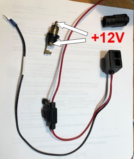
4) Lastly, in wiring the DIN plug, I expect that I'd connect the red wire of the Valentine harness (with its 2A fuse inline) to the central power connector on the DIN plug, and the black wire of the Valentine harness to the outer, cylindrical connector of the DIN plug, is that correct? The DIN plug that I'm using had a different cable attached to it before I disassembled it, and I noted carefully that that's how it was wired then - red to centre, black to outer. I assume that the black wire goes to a frame negative/ground, sort of thing?
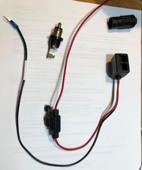
I have attached a photo of the DIN plug and the Valentine wiring harness so folks who know this stuff can see exactly what I'm doing. The Valentine harness technically ends in an RJ11 socket, and the Valentine RD plugs into that, not directly into the BMW accessory port, but that's a non-issue I suspect.
Aside from my somewhat lame questions (the detector is about $700 to a Canadian, so, you know . . . ), does anyone have any other points about mistakes not to make?
thanks in advance to some wonderful owners, I can't believe how excellent it is to have you folks out there!
Peter in BC


