yourpalcal
New member
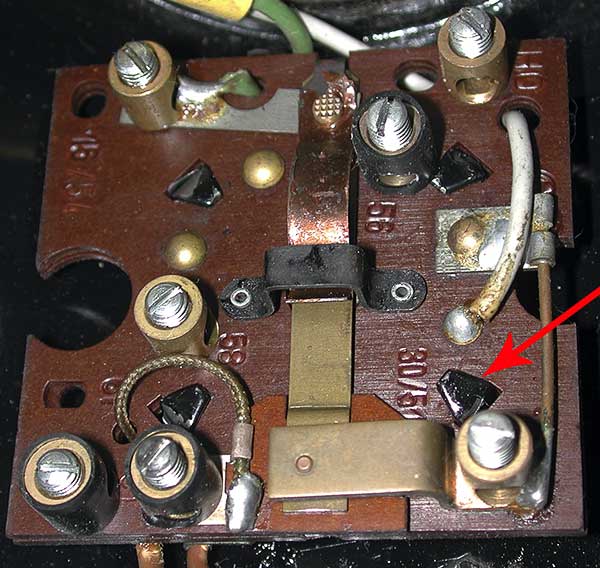
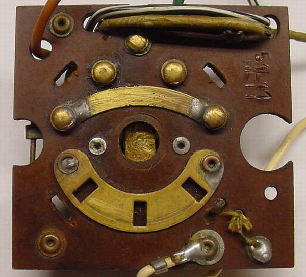
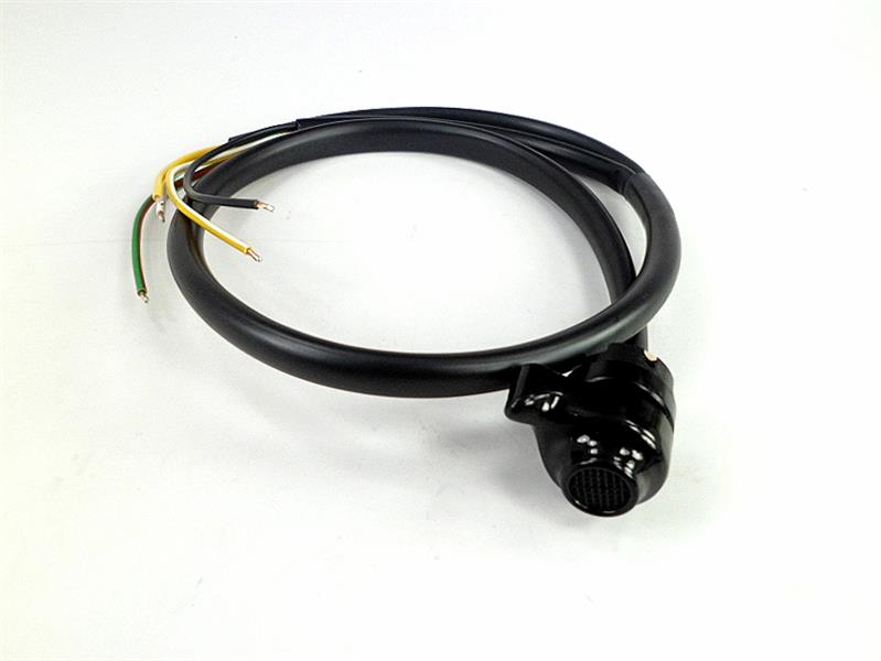
Hope I’m not wearing out my welcome on this message board but this build keeps offering new and challenging projects. I noticed a crack in my left horn/dimmer switch on my 72 r75/5. Closer inspection shows the inner spring is coming out and when I removed it from the bars the thumb portion basically broke in half probably due to age. Therefore, I went ahead and ordered a new replacement switch. I just opened my headlight assembly and must admit feeling a little overwhelmed. I can see where the switch cable routes in from the back but it looks like it splits with some wires going up to the speedo and others to a small connector.
Any advice on simplifying this replacement. Should I just cut the old wires, solder and use butt connectors?
Any advice on simplifying this replacement. Should I just cut the old wires, solder and use butt connectors?

")