• Welcome, Guest! We hope you enjoy the excellent technical knowledge, event information and discussions that the BMW MOA forum provides. Some forum content will be hidden from you if you remain logged out. If you want to view all content, please click the 'Log in' button above and enter your BMW MOA username and password.

    If you are not an MOA member, why not take the time to join the club, so you can enjoy posting on the forum, the BMW Owners News magazine, and all of the discounts and benefits the BMW MOA offers?

  • Beginning April 1st, and running through April 30th, there is a new 2024 BMW MOA Election discussion area within The Club section of the forum. Within this forum area is also a sticky post that provides the ground rules for participating in the Election forum area. Also, the candidates statements are provided. Please read before joining the conversation, because the rules are very specific to maintain civility.

    The Election forum is here: Election Forum

1975 R75/6 Refresh Projects

brook.reams

B Reams
1975 R75/6 Refresh Project

This bike, a 1975 R75/6, is the first BMW I bought and now has almost 106,000 miles on it.

IMG_2245.jpg

It is the first bike I rode more than 1,000 miles in one day back in 1976 and is the first build project I completed in 2010 and documented here:
I have several projects that I didn't get to during the build. One of these is replacing the timing chain which I document in the link below with a lot of pictures and detailed step-by-step procedure.

My bike has the duplex, dual row chain, while starting with the /7 series, the timing chain is a single row chain. This procedure should help you replace a /5, /6 or /7 series timing chain, but some of the parts will be different as I note in the write-up.

Since I stripped the bike I have the engine out of the frame, but most people will do this work with the engine in the frame. Although it is an option to remove the front wheel and forks to have clear access to the front of the engine, I think the work can be done without removing them.

Before starting this project, I reviewed material available on the Airheads Beemer Club site, www.airheads.org: I believe you can access the links in the write-up even if you are not a member, but consider joining this group if you want to contribute to the Airhead culture. I read material on Bob Fleischer's blog site, and I posted a number of questions to the Micapeak Airheads forum whose members are legend for providing thoughtful advice and encouragement. You should add these resources to your toolkit as they are authoritative with valuable information.

In particular, I want to acknowledge Ron Cichowski, Tom Cutter, Bob Fleischer, Doran Shields, Marten Walkker and Eric Zwicky on the Micapeak Airheads forum for answering my questions. Also, a local Colorado Airhead, Don Wreyford, came by to kibitz and help with the disassembly process. Don has always been generous with his time and knowledge. And, my youngest son, Branden, shown in many of the photos with the electric yellow shirt, helped me on the entire project with wrenching, picture taking, and good ideas and advice when we needed to stop and reconsider what we should do next. He is turning into an accomplished Airhead wrench and lover of Bavarian iron.

Here a couple of the pictures included in the detailed write-up you can access from the link above.


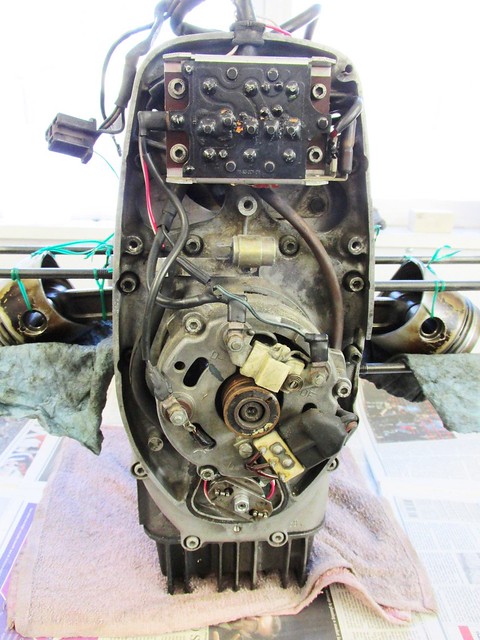
Ready To Start - Timing Cover Removed
by Brook Reams, on Flickr


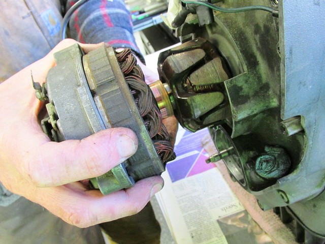
Alternator Stator and Housing Removed
by Brook Reams, on Flickr


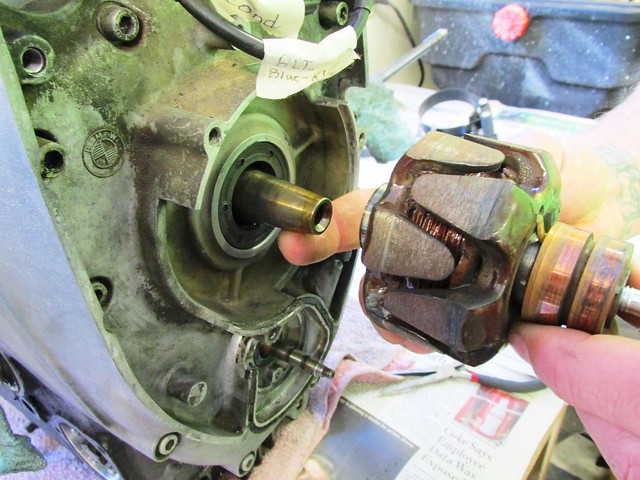
Alternator Rotor Fits on Taper of Crankshaft Nose
by Brook Reams, on Flickr


Engine Electrics Harness with Labels
by Brook Reams, on Flickr


Finger Tight and Cover Came Loose
by Brook Reams, on Flickr


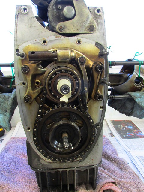
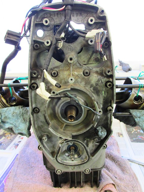
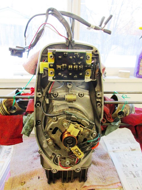
What's Under the Timing Cover
by Brook Reams, on Flickr


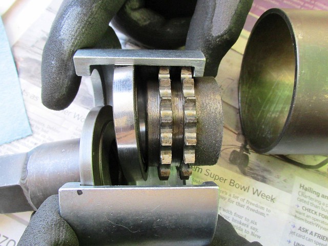
Crankshaft Nose Bearing and Sprocket in Cycle Works Removal Tool
by Brook Reams, on Flickr


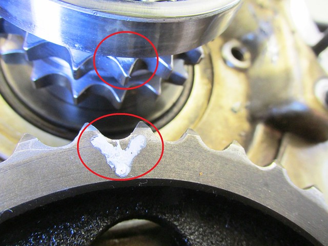
Crankshaft Sprocket and Camshaft Sprocket Timing Marks Aligned at TDC
by Brook Reams, on Flickr


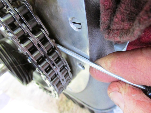
Installing Bronze Color Back Plate With Screw Driver Blade
by Brook Reams, on Flickr


Finshed Engine Electrics Install
by Brook Reams, on Flickr
 
Last edited:
Shop Manuals

+1 - what he said. ;). I'll be doing one in 3-4 years. Wish you'd write some shop manuals

Well, it could be that's what I am really doing, but one project at a time. At this rate I may get done around 2100 (as in year, not time) ;-)

Best.
Brook Reams
 
Lol - ever read the Barrington restoration manual for /2's? It's a lot like a string of you posts. :)


Sent from my iPad using Tapatalk
 
I would also like to add my thank you for a well documented website showing your process. I know that this documentation was a lot of work and it will likely be useful to many others.
 
Brook's Write-up Stash

I haven't been doing a very good job, but if you go to this thread:

http://forums.bmwmoa.org/showthread.php?50991-Rebuild-Sites-with-Photos

and search for Brook, you'll see many of his rebuild threads list.

Kurt,

Good to hear from you again. I hope the holidays went well for you and yours.

For those interested in the materials I have produced, you will find them here:
I believe you can cut and paste any of them into a word document to print out if you wish. I removed the PDF tool Word Press provides as it includes ads which I deplore.

You will find write-ups listed on the right column, or the bottom of a post, on the three projects I've done/am doing for a 1973 R75/5 LWB, 1975 R75/6 (used for this post) and a 1983 R100RS (the next restore/rebuild after I get the 75/6 "freshen up") done. There is also a "Rebuild Index" page for each bike organized with links so you can quickly find something you are interested in.

Even when I finish a project like the R75/6 "Grey Ghost" back in 2010, there is always more I can do, which seems to be the nature of all airheads. For some reason, "nut jobs" like me find more joy in wrenching when they take three times as long to complete the project so they can take a lot of pictures and provide documentation to help others have an easier time when they do a similar project.

Best.
Brook.
 
Ok, so I can go watch TV and see some inane show about which I care little (I am outside the target demographic for these shows - and - I have very little tolerance for the commercials -I don't even "get" many of the adverts) OR I can spend the evening reading through the many re-build articles. [Caveat - it is dang cold in my garage, otherwise I'd have the other option of actually doing some similar work on my bikes - My next garage will have more space AND a heater!]

If you couldn't guess - I'll be reading the on-line re-build articles - Good Job Brook!
 
Brook well done as usual . It did not appear the chain was rubbing the front case on the left.My /5 was nasty loose.
 
I see you used the CycleWorks puller to remove the timing case. I found that using a heat gun on the bearing area for about 3-4 minutes and a slight tap from the back of the cover (starter area) with a rubber hammer was all it took to free mine.

Seems like this is the year for timing chain replacements. I just did mine not too long ago (also wrote up a more text oriented procedure in my blog) and have seen at least 2-3 others doing it on this forum and others.
 
Last edited:
Folks,

80092:
To the point about not finding my chain rubbing on the inner timing cover, that's true. And that's a good thing.

Type181R90:
To the comment about just heating the inner timing cover around the crankshaft nose bearing and then tapping the cover to break it loose from the gasket, I suspect that would work for lots of folks. As I showed, we didn't heat the inner timing cover and we only had to hand tighten the puller bolt on the Cycle Works tool to get the cover to come loose. My thought is that the tools are helpful in ensuring the inner timing cover is tight against the engine block when tightening and torquing the 12 fasteners that hold it in place. The cover cools pretty quick and that's a lot of hardware to torque.

robsryder:
That was nicely written. I loved it. But, perhaps you are really saying that my literary content is not much better than a Viagra commercial ;-) (snerk snork ...)

barryg:
Thank you. And yes, I seem to have the "detail" gene when it comes to documenting mechanical work. It was a curse when I was in product marketing, but the field engineers had my number on speed dial :)
 
Type181R90:
To the comment about just heating the inner timing cover around the crankshaft nose bearing and then tapping the cover to break it loose from the gasket, I suspect that would work for lots of folks. As I showed, we didn't heat the inner timing cover and we only had to hand tighten the puller bolt on the Cycle Works tool to get the cover to come loose. My thought is that the tools are helpful in ensuring the inner timing cover is tight against the engine block when tightening and torquing the 12 fasteners that hold it in place. The cover cools pretty quick and that's a lot of hardware to torque.

Could be, but the only interference fit is the bearing against the timing cover, you install it that way, it should come off that way too (at least if you're not going to replace the bearing or sprocket and need to preserve the bearing).

I'm not saying either way is right or wrong, but for people that don't want to dish out the cash for the CycleWorks set, a Harbor Freight $8.99 heat gun and 4" gear puller work just fine. That being said, nearly everything to do with the bottom end on my 1957 R60 is an interference fit, so I'm used to heating things, freezing others, assembling, reheating, and so on and so on.

FYI, I do think the CycleWorks crank sprocket puller is a better option than a conventional gear puller, but last time I checked, you have to buy the whole kit to get it. Maybe that's changed recently though...
 
Cycle Works Tools for Timing Chain Replacement

FYI, I do think the CycleWorks crank sprocket puller is a better option than a conventional gear puller, but last time I checked, you have to buy the whole kit to get it. Maybe that's changed recently though...

There are two "kits" available these days. One is just the tools for the timing chain, sprocket and nose bearing work:
http://www.cycleworks.net/index.php...id=367&zenid=1f59bde027ef66c6964ca350c195bad2

The current price of this kit is reasonable to me.

The other kit includes all the tools for doing engine work (including the timing chain tools) and is about 75% more than the price of the timing chain kit.

Best.
Brook Rems
 
1975 R75/6: Replace Rear Main Oil Seal, Oil Pump Cover, O-ring, Refurbish Clutch

Folks,

I have completed documenting this work for those interested in the parts, tools and procedure used. You can find my write-ups here.

I did the same work on my R75/5 as well which you will find on my site. The main differences between these projects were using Southland Clutch to refurbish the R75/6 clutch where I replaced the clutch on the R75/5 project, and not damaging the rear crankshaft thrust washer this time :)

This is the first time I used Southland Clutch. I am very pleased with their knowledge of airhead clutches, their courteous and prompt service and the quick turn around at a price about one-half the cost of the new parts. I am adding them to my Resources list.

I relied on information published by several Airhead mechanics and gurus including Bob Fleischer, Duane Auscherman and Tom Cutter in particular. Of course, any errors in my work are mine alone and do not reflect on their knowledge and expertise.

I hope this information is helpful to those who want to do this work. Below are a couple pictures from the write-ups.

<a title="Clutch Install/Removal Bolts, Nuts, Washers" href="https://www.flickr.com/photos/brook-reams/25155978686/in/album-72157663255032409/"><img src="https://farm2.staticflickr.com/1540/25155978686_1bb4527071_z.jpg" alt="Hardened Clutch Install/Removal Bolts, Nuts, Washers" width="640" height="480" /></a>
Hardened Clutch Install/Removal Bolts, Nuts, Washers

<a title="Flywheel Puller Parts" href="https://www.flickr.com/photos/brook-reams/24616051125/in/album-72157663255032409/"><img src="https://farm2.staticflickr.com/1472/24616051125_215fb98395_z.jpg" alt="Flywheel Puller/Installer Tool Parts" width="640" height="480" /></a>
Flywheel Puller/Installer Tool Parts

<a title="Rear Main Seal Puller Parts" href="https://www.flickr.com/photos/brook-reams/24320520270/in/album-72157663255032409/"><img src="https://farm2.staticflickr.com/1463/24320520270_da251ec4e7_z.jpg" alt="Crankshaft Rear Main Seal Puller/Installer Parts" width="640" height="480" /></a>
Crankshaft Rear Main Seal Installer/Puller Parts

<a title="Bolt in Alternator Nose Keeps Crank Immobilized" href="https://www.flickr.com/photos/brook-reams/24616052915/in/album-72157663255032409/"><img src="https://farm2.staticflickr.com/1502/24616052915_454cebc2e4_z.jpg" alt="Small Bolt in Alternator Nose Keeps Crank From Moving Forward" width="640" height="480" /></a>
Small Bolt in Alternator Nose to Keep Crank From Moving Forward

<a title="Puller Plate Installed to Immobilize Flywheel" href="https://www.flickr.com/photos/brook-reams/23989265703/in/album-72157663255032409/"><img src="https://farm2.staticflickr.com/1448/23989265703_0b6f8dcb7f_z.jpg" alt="Puller Plate Installed to Immobilize Flywheel" width="640" height="480" /></a>
Puller Plate Installed to Immobilize Flywheel

<a title="Groove Cut in Flywheel by Old Style Seal" href="https://www.flickr.com/photos/brook-reams/24248295589/in/album-72157663255032409/"><img src="https://farm2.staticflickr.com/1537/24248295589_dc7a8e6529_z.jpg" alt="Groove Cut in Flywheel by Old Style Seal" width="640" height="480" /></a>
Groove Cut in Flywheel by Old Style Seal

<a title="Aligning Puller and Inserting Screw Into Seal" href="https://www.flickr.com/photos/brook-reams/23989263293/in/album-72157663255032409/"><img src="https://farm2.staticflickr.com/1643/23989263293_a1f6e0671a_z.jpg" alt="Aligning Puller with Two Flywheel Bolts and Inserting Screw Into Seal" width="640" height="480" /></a>
Aligning Puller with Two Flywheel Bolts and Inserting Screw Into Seal

<a title="Forming Crank Rear Oil Seal on Flywheel Ring" href="https://www.flickr.com/photos/brook-reams/24914537122/in/album-72157663255032409/"><img src="https://farm2.staticflickr.com/1651/24914537122_bd1d78a373_z.jpg" alt="Forming Crank Rear Oil Seal on Flywheel Ring" width="640" height="480" /></a>
Forming Crank Rear Oil Seal on Flywheel Ring

<a title="Torquing New Flywheel Bolts" href="https://www.flickr.com/photos/brook-reams/24401965014/in/album-72157663255032409/"><img src="https://farm2.staticflickr.com/1650/24401965014_8d9ddbf1b8_z.jpg" alt="Torquing New Flywheel Bolts" width="640" height="480" /></a>
Torquing New Flywheel Bolts in Stages to 75 FT/Lbs

<a title="Torquing Clutch Bolts" href="https://www.flickr.com/photos/brook-reams/24939629691/in/album-72157664115308886/"><img src="https://farm2.staticflickr.com/1460/24939629691_021ebb1dc1_z.jpg" alt="Torquing Clutch Bolts to 16 FT/Lbs" width="640" height="480" /></a>
Torquing Clutch Bolts to 16 FT/Lbs


Best.
Brook Reams.
 
34 BMW R75/6 Rebuild Master Cylinder & Disk Caliper

Folks,

I finally got done documenting this project. If you are considering work on the front disk brake system on your /6 or /7 or R80 thru 1980 which use either the ATE 38 mm or 40 mm caliper piston, I think this material can be helpful.

I just put 150 miles on this bike after completing the "Freshen Up" and it's running very smoothly and stops as well :).

Enjoy and have a safe and relaxing ride on the 4th of July.

I'll be adding additional documentation of several other projects I completed on this bike in due course.

Here are a couple pictures:

<a title="Master Cylinder & Fluid Reservoir" href="https://www.flickr.com/photos/brook-reams/26971846481/in/album-72157668453072305/"><img src="https://c2.staticflickr.com/8/7101/26971846481_7f445a1ec3_z.jpg" alt="Master Cylinder & Fluid Reservoir Mount Under Gas Tank" width="480" height="640" /></a>
Master Cylinder & Fluid Reservoir Mount Under Gas Tank. Note the Evidence of Brake Fluid Leak

<a title="Earler Two Hole Master Cylinder" href="https://www.flickr.com/photos/brook-reams/26971845311/in/album-72157668453072305/"><img src="https://c8.staticflickr.com/8/7658/26971845311_c793ae9170_z.jpg" alt="Earler Two Hole Master Cylinder" width="640" height="426" /></a>
Earler Two Hole Master Cylinder

<a title="Master Cylinder Piston Removed" href="https://www.flickr.com/photos/brook-reams/26971844721/in/album-72157668453072305/"><img src="https://c2.staticflickr.com/8/7629/26971844721_ce8b0106ec_z.jpg" alt="Master Cylinder Piston Assembly Removed" width="640" height="426" /></a>
Master Cylinder Piston Assembly Removed

<a title="Master Cylinder Rebuild Kit Parts" href="https://www.flickr.com/photos/brook-reams/26971845131/in/album-72157668453072305/"><img src="https://c4.staticflickr.com/8/7519/26971845131_b08e99f3e7_z.jpg" alt="Master Cylinder Rebuild Kit Parts" width="640" height="426" /></a>
Master Cylinder Rebuild Kit Parts

<a title="Master Cylinder Installed on Frame Tube" href="https://www.flickr.com/photos/brook-reams/26971842621/in/album-72157668453072305/"><img src="https://c6.staticflickr.com/8/7168/26971842621_db57ba022c_z.jpg" alt="Master Cylinder Installed on Frame Tube" width="640" height="426" /></a>
Master Cylinder Installed on Frame Tube

<a title="A Blast of Compressed Air Removes Piston" href="https://www.flickr.com/photos/brook-reams/27236133726/in/album-72157668453072305/"><img src="https://c7.staticflickr.com/8/7408/27236133726_084ff29ef7_z.jpg" alt="A Blast of Compressed Air Removes Piston" width="640" height="426" /></a>
A Blast of Compressed Air Removes Piston

<a title="Puck with Dust Seal Installed in Caliper" href="https://www.flickr.com/photos/brook-reams/26434701224/in/album-72157668453072305/"><img src="https://c1.staticflickr.com/8/7685/26434701224_64f7f1f12e_z.jpg" alt="Piston with Dust Seal Installed in Caliper Bore" width="640" height="426" /></a>
Piston with Dust Seal Installed in Caliper Bore

<a title="Caliper With Painted Metal Line Installed" href="https://www.flickr.com/photos/brook-reams/27224474231/in/album-72157668453072305/"><img src="https://c8.staticflickr.com/8/7449/27224474231_6b950c6204_z.jpg" alt="Caliper With Painted Metal Line Installed" width="426" height="640" /></a>
Caliper With Painted Metal Line Installed


Best,
Brook Reams.
 
Last edited:
Excellent write up. I tend to learn visually and if I can see how it's done it makes it so much easier to learn. Just now checked out your website and this is such a wealth of information. However one maintenance item I've been searching for and can't find is the /6 wheel bearing maintenance. I've read Snowbums treatise on the issue but don't understand everything I should. Have you done an article on wheel bearing maintenance?
 
Excellent write up. I tend to learn visually and if I can see how it's done it makes it so much easier to learn. Just now checked out your website and this is such a wealth of information. However one maintenance item I've been searching for and can't find is the /6 wheel bearing maintenance. I've read Snowbums treatise on the issue but don't understand everything I should. Have you done an article on wheel bearing maintenance?

Hi M Crenshaw,

Thanks for the kind words. Many people do much better with pictures to clarify how parts go together. Today, with the cost of digital pictures $0.00, it's become easier to include as many of these as needed. That's one reason I have been taking time to publish my projects with lots of pictures. I think of these write-ups as "footnotes" to the comprehensive written text available on-line from several of the long-time masters of Airhead mechanics. And, I lurk on the Micapeak airhead forum as well (http://micapeak.com/mailman/listinfo/airheads) so I can get details I need when I do a project.

To your question about wheel maintenance, I suspect you are asking about wheel bearing removal, replacement and pre-loading. No, I haven't done that project yet, but it's on my list of "to do" projects for documentation. That said, there are many different versions of the wheel hub and bearings, so I will, as always, show what I did on the specific model bikes I work on.

Best.
Brook Reams.
 
Back
Top