• Welcome, Guest! We hope you enjoy the excellent technical knowledge, event information and discussions that the BMW MOA forum provides. Some forum content will be hidden from you if you remain logged out. If you want to view all content, please click the 'Log in' button above and enter your BMW MOA username and password.

    If you are not an MOA member, why not take the time to join the club, so you can enjoy posting on the forum, the BMW Owners News magazine, and all of the discounts and benefits the BMW MOA offers?

  • Beginning April 1st, and running through April 30th, there is a new 2024 BMW MOA Election discussion area within The Club section of the forum. Within this forum area is also a sticky post that provides the ground rules for participating in the Election forum area. Also, the candidates statements are provided. Please read before joining the conversation, because the rules are very specific to maintain civility.

    The Election forum is here: Election Forum

R1150RT Clutch Kit Balance

sundance71

New member
Hi folks.

I'm getting ready to change out the clutch on my 04 R1150Rt with the longer splined hub. I went ahead and got the pressure plate and clutch cover as well from Beemer Boneyard. The parts came in today and look good but I was wondering about one thing.

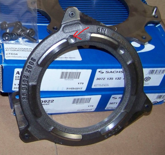
In all of the photos and videos that I've seen, the cover and pressure plate are balanced by drilling indents in specific locations on the part.

clutch.png

The parts that I received don't look like any material was removed from anywhere. How can they be balanced unless I just lucked out and got two perfect parts? I may be overthinking this but getting to the clutch is a major PITA and I don't want to get everything back together and have vibration issues. Does anyone else have any experience with this?

Thanks
Chris
 
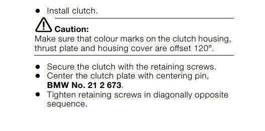
Each part should have a paint mark including the clutch housing.
From the OE manual
 

Attachments

  • Paint marks.jpg
    Paint marks.jpg
    37.7 KB · Views: 176
I feel your pain. I too have an 04 1150RT and I replaced the clutch components several years ago with BBY parts. I thought I had reinstalled all the components correctly, only to get out on the first test ride and felt like engine vibrations were noticeably higher compared to before the replacement. I lived with it for a couple of years by altering how I rode and rpm range avoidance and then finally decided to go back in and reassess the situation. As you are or will become familiar with the level of effort to strip down the bike to get to the clutch, I decided the very best and most positive approach was to pull the flywheel and clutch plates and have them balanced as a system. Cost was minimal. Long story short, after installation, buttoning up the rest of the bike and conducting a test ride, I could not be happier with how smooth the bike became. In hindsight, I think my error the first time around was not getting all 3 component, especially the flywheel separated by ~120 degrees.

As an aside, when you go in and replace the clutch, think about other maintenance items that can be done while the bike is stripped down and its mostly a matter of added parts cost vs. parts and labor to get back in there. You'll have great access to many things.

Hoping the wrenching gods are with you...
 
Thanks for the replies.

I got the bike apart and the good news is that the input splines look good. I decided to reuse my old clutch parts (except for the friction disc) and Mike at BB was kind enough to let me return the pressure plate and cover with no trouble. This post wasn't intended in any way to cast doubt on the quality of the parts that BB sells. Mike actually, explained that sometimes the parts are drilled, sometimes there is some material ground off of the edges and sometimes they don't need anything removed. The parts that I got from BB had the paint marks on them so you could space them 120 degrees to either side of the flywheel mark as referenced in the manual. I ended up reusing my old stuff mainly because they didn't need replacing and the fact that I know that the bike didn't have any vibration issues when I took it apart. It's not to say that it would have with the new ones but it's one less thing to worry abut.


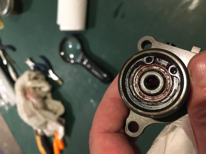
I'm replacing the friction disc and slave cylinder with BB parts. It's good that I got in there (at least to the slave cylinder) as the cavity was full of what I am assuming is the remnants of 17 year old grease.


IMG_6045.jpg


Overall, it went well and I'm hoping my wrenching karma holds out through the reassembly.
 
Thanks for the replies.


I'm replacing the friction disc and slave cylinder with BB parts. It's good that I got in there (at least to the slave cylinder) as the cavity was full of what I am assuming is the remnants of 17 year old grease.


View attachment 84751


Overall, it went well and I'm hoping my wrenching karma holds out through the reassembly.

That is old brake fluid.
Wet it with water and you will see it is water soluble.
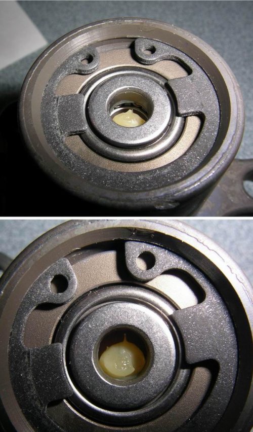
Add extra grease to the new clutch slave bearing. They typically are undergreased from the factory.
 

Attachments

  • Slave bearing1.jpg
    Slave bearing1.jpg
    130 KB · Views: 122
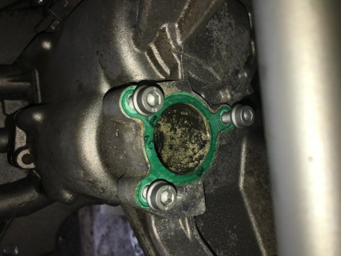
The slave cylinder from BB looks a little different than the stock one. I had read the posts about the stockers being under greased but the bearing on this one appears to be sealed at the top. I have one of the rubber grease gun nozzles and had planned to pump the pushrod cavity full of grease under pressure. If the back of the bearing isn’t sealed as well, it should get some grease to it. Any worries about mixing different types of grease? I’m using timken red wheel bearing grease.

The rear input shaft seal looks a little weird also (probably from all that brake fluid) so I’ll be replacing that too. It looks like it might be difficult since it is down in the well a ways. Anyone have any tips on replacing this?

Thanks


BA9AF598-3541-4F7F-82FE-90BD58C97329.jpg
 
No issues with using high temp wheel bearing grease. Used it many times.
My original slave now has 370,000 km on it with 80,000km lube intervals.

That seal can be difficult to remove.
Carefully measure the depth as it does not bottom. (This applies to all the transmission seals)
Space must be left behind for oil to circulate to the back side of the TM bearing
Tap the seal in slightly on one side and then carefully use a pick with a steady even pull.
Take good care not to scratch the shaft or transmission bore.

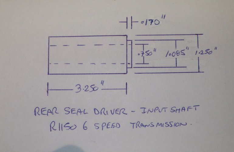
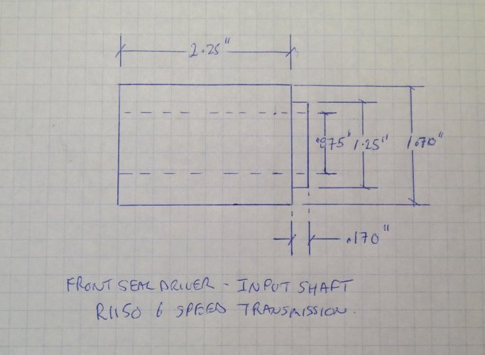
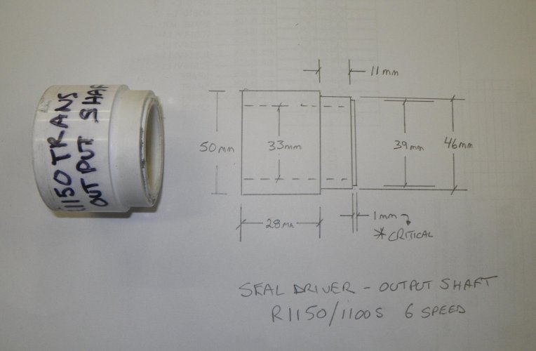
Seal drivers as below can be made from PVC plumbing fittings on any small lathe.
 

Attachments

  • Input shaft rear seal driver R1150.jpg
    Input shaft rear seal driver R1150.jpg
    86.2 KB · Views: 107
  • Input shaft front seal driver R1150.JPG
    Input shaft front seal driver R1150.JPG
    468.7 KB · Views: 101
  • Output shaft seal driver R1150.jpg
    Output shaft seal driver R1150.jpg
    175.9 KB · Views: 107
GSA, thanks for the input, your posts have been really helpful.

I don't have access to my lathe right now but I think that I might be able to 3d print the seal drivers. If I do it with like 98% infill I think that they could be strong enough. I'll let you know how they turn out.

Chris
 
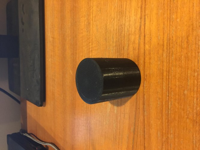
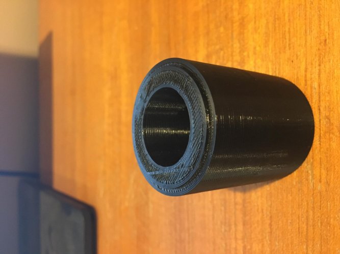
Here is my first shot at a 3D printed output shaft seal driver. It is printed at 100% infill so it is basically a solid part. I'll let you know if it works. Thanks again for the dimensions


IMG_6075.jpg

IMG_6074.jpg
 
GSA,

There is a hole to clear the shaft (second pic). When I said that they are solid, I meant that it is printed at 100% infill.

Most printed parts are done at something less than 100% and have an internal structure with voids so they are not like parts that are machined from a solid piece of material. At 100% it should be similar to a part machined from a solid block of PLA.

The top surface of my output shaft seal looked pretty close to flush with the metal surface around it. You recommend that it be sunk 1mm below this. Is this correct?

Thanks
Chris

The depth dimensions were derived from several different transmissions which were original.
 
Back
Top