• Welcome, Guest! We hope you enjoy the excellent technical knowledge, event information and discussions that the BMW MOA forum provides. Some forum content will be hidden from you if you remain logged out. If you want to view all content, please click the 'Log in' button above and enter your BMW MOA username and password.

    If you are not an MOA member, why not take the time to join the club, so you can enjoy posting on the forum, the BMW Owners News magazine, and all of the discounts and benefits the BMW MOA offers?

Centech AP2 & AP130R Installation Question 2009 R1200RT

flemmings27

New member
List,

I'm in process of installing Centech's AP2 fuse panel and the APR130R harness on my 2009 R1200RT. The fuse is all wired up, except for the orange wire ( which is the relay trigger) so right now, only 2 fuse connection points are hot, while the stronger 3 are dormant. Since I've mounted the fuse panel under the rear seat, the logical place to go with the orange wire, seems to be to the rear tail light. However, I'm not quite sure I understand the whole canbus thing, but it seems to me that since my computer can tell me when a rear brake light is out, then the tail lights must also be going through the canbus.

Thus, I have 3 concerns/questions about attaching the Orange wire to my brake light wire (ie, by stripping some of the plastic off the wire leading to the tail light).

1. Can this be done safely without potential to damage the bike's canbus system? Are the tail lights actually going through the controller for the canbus?

2. I plan to call Centech's tech for part of the following question, but will ask here in case anyone knows by their own experience. Does the relay have a clamping diode? I ask because I assume that there will be a voltage spike every time the relay shuts off. I'm also assuming that the controller/computer on the bike uses resistance to tell if the bulb does not work, and that adding the relay will change the resistance in the circuit, and thus, the voltage spike could cause damage to the controller.

3. I also considered using the rear socket accessory point, but the size of the wiring harness made me wonder about what that was wired into.

Finally, has anyone put an AP2 on their R1200RT (w/canbus) and gone through the rear tail light? If so, how/where exactly did you connect? On the posts of the light? On the wire?

Thanks in advance

Signed,

Bike's only a year old and don't want to screw it up!
 
Joyce - check you're pm's but on a short list, there is no clamping diode but if you want to add one you can - I haven't on 4 bikes to date.

The CAN is just a communication line for the bikes computers to its peripherals. The canbus only provides the signals the control is done by the computer(s)

My wife's centech is connected to the accessory socket.

I used the parking light wires because this gives me instant on/off rather than a delayed off

The trigger wire is connected to a coil in the relay to activated - the equivalent resistance of this on the circuit will not be enough to trip a fault.
 
NAPA guys (at least where I live) sell protected relays that will fit the Centech socket.
OR you can go to Radio Shack and buy a 1 amp, 1500 PIV diode and put it in the trigger wire oriented correctly. They're about 50 cents each. That's how mine is done.
Like Semper Fi, not heard of anyone frying a bike without one BUT I have on cars heard extremely audible evidence of back EMF coming through the speakers when relays are switched, especially those supplying HID sets, etc. Because BMW does not publish circuits for the bike's main computers, there is no way to assess whether they have any sort of decent protection built in (they probably do), so I err on the safe side and isolate with diodes, always.

Re the trigger wire site, I prefer the "instant off" with the ignition so do not hook to the accessory socket wire because that delay can be 15 seconds to 20 minutes or more if the computer is in one of its "checking" modes.
My preferred trigger location is the higher voltage side of the starter relay coil. This is a very protected spot inside a cube next to the diagnostic connector on your bike. It is close to the rear fender. If that's where you've mounted your Centech its a short, neat run.

The Centech harness is a well made piece with adequate wire gauges and their relay, though unprotected, is a good, reliable part (there are a lot of junk chinese relays around). I use mine with an Eastern Beaver box rather than a Centech AP-2 because I prefer the ability to closely fuse individual circuits and I am using 7 of those on my EB box. (an alarm, radar detector, hyperlights, HIDs, FF50s, unswitched outlet). Before adding an alarm and the unswitched outlet, the bike- an 08 RT- had an AP-1 that worked well.

Because you are asking detailed and careful questions, the following cautions about following good wiring practices may be be superfluous
1) Use proper gauge wires, especially for high amp accessories.
2) Fuse every circuit to a proper value for the wire gauge used and never more than double to load of the accessory in any case.
3) Heat shrink crimped connections and considering soldering everthing you do including tinning the ends at the Centech box, loom all wire runs, and use plenty of cable ties to keep stuff from vibraing around.
4) If you have to tap for something you may want to remove use posi-locks, not the blade crimp type taps that damage wires so much.
 
One other comment on the choice of where to pull the trigger voltage for the relay from.

I'd suggest avoiding the brake light. On many R12xx bikes, the ZFE (body module) will detect if a brake or running light filament has gone bad. It will then switch the other filament (or bulb) into a combined brake/running light mode, where the running light receives lower voltage, which is switched up to full system voltage when working as a brake light. LOTS of electrical components will be unhappy with the lower voltage in running-light mode, and it's possible this failsafe system won't work if the component fools the system into thinking a bad bulb is still good (and I could go into depth about how BMW detects bad bulbs on their cars - but I'm unsure if they adopted the same technology for the bikes.)

Anyway - as Luis suggested - if you don't mind a slightly delayed off, the accessory socket is a natural takeoff point, if you want instant-off, the front parking light connection works fine. Stay away from the brake light wiring.
 
Thanks to everyone for these detailed responses. If it will help anyone here on their future Centech additions, I called the Centech techie, and he said that their relay does have a resistor in it, which should prevent or minimize voltage spikes. He also said that they don't use clamping diodes any more, and that he has not heard of any BMW bike owners having problems with the AP1 or AP2 devices and their accompanying wiring harnesses.

Regards

Joyce
 
Joyce,
What Centech supplied me is NOT a protected type. It is not uncommon to get wrong answers on electronic parts and you may have been given wrong information. Or perhaps Centech has changed parts. You can look yours up on the various makers websites. Or post it here and I'll put up a spec link. Here is the link to the specs for mine.

http://www.datasheetcatalog.org/datasheets2/12/121197_1.pdf

I got a Matsu****a (Panasonic) CB1aH-M-12V relay with my harness. This is a Single Pole, Single Throw Throw, Normally Off, sealed type with high capacity contacts in a bracket mount
There is nothing in its specs re protection by resistor or diode nor is its housing marked with any of the the normal relay diagrams that can be used to confirm such. Like many Japanese relays it has only its part number on it but the Matu****a codes on it do not equate to a protected relay. If it was a protected relay there would be a D or R adjacent to the M indicating its protection type.

It is a very good part rated at 70A at normal temp, 50,000 cycles at full load, and is vibration resistant, silver alloy contacts, etc etc. It is a fairly common type and can be purchased through Digi-Key ($5.59) or many other US suppliers.

For those who might be replacing relays in a Centech harness, note that the format is a common 4/5 pin automotive type and many other types with inadequate rating will plug into the Centech socket. Lots of them are rated at only 30A and may well fry if you are putting significant amps through the box (eg a couple pair of driving lights) Do be certain to get a 70A type as a replacement should you need one (unlikely).
 
Hey modereators- we've got a weird filter on thgis site when it starts chopping out part of the middle of a well known electrical suppliers name and subbing asterisks.

Anyway, here is a tranposition misspelling that should dupe the dumb filter. "Matsuhitsta"
 
One more comment on the Centech A wiring kit.

The main power lead from the battery is, of necessity, unfused because there are no single fuses of the capacity of the panel commonly available. In principle one could use a fusible link, car style, but in practice no one does that. It is a short run to the rear fender so additional protection is not normally used.

Because a short in that wire (just like a battery cable) is a serious fire hazard due to its ability to carry very high current, the wire should be loomed, carefully located and properly secured to prevent mechanical injury to the wire.
 
Hey modereators- we've got a weird filter on thgis site when it starts chopping out part of the middle of a well known electrical suppliers name and subbing asterisks.

Anyway, here is a tranposition misspelling that should dupe the dumb filter. "Matsuhitsta"

Yes there is a filter for foul language - and as you guessed it, the word was filtered out even though it is perfectly appropriate in the context used.

Regards
 
Re the trigger wire site, I prefer the "instant off" with the ignition so do not hook to the accessory socket wire because that delay can be 15 seconds to 20 minutes or more if the computer is in one of its "checking" modes.
My preferred trigger location is the higher voltage side of the starter relay coil. This is a very protected spot inside a cube next to the diagnostic connector on your bike. It is close to the rear fender. If that's where you've mounted your Centech its a short, neat run.

It would be really helpful if you could post a picture of the trigger location. I've been thinking about adding a fuse block this winter.

Thanks,

Steve
 
Yes there is a filter for foul language - and as you guessed it, the word was filtered out even though it is perfectly appropriate in the context used.

Regards

It did not filter a word. It did not filter foul language. It filtered 4 contiguous letters. Can you not train it any better? What if we want to talk about toasting ****ake mushrooms a Matsu****a (Panasonic) toaster oven?

sellis said:
It would be really helpful if you could post a picture of the trigger location. I've been thinking about adding a fuse block this winter.

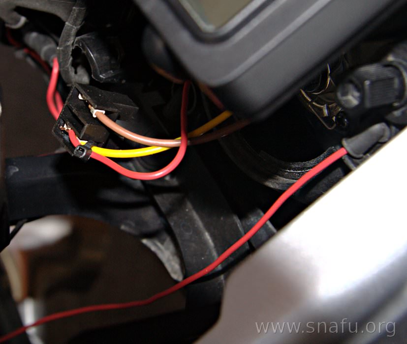
Since it is easy to get to on a GS I used the low beam as a trigger for my fuzeblock. The relay is not energized until *after* the bike is started. Power is removed as soon as the key is switched to the off position. This works because the low beam stays on with the high beam. I think the RT is the same.

Access to the socket was through one of the vent tubes. The red wire is my trigger wire.

p-20070608-1508-2872.jpg


Don't know if this is feasible on the RT.
 
Last edited:
One more comment on the Centech A wiring kit.

The main power lead from the battery is, of necessity, unfused because there are no single fuses of the capacity of the panel commonly available. In principle one could use a fusible link, car style, but in practice no one does that. It is a short run to the rear fender so additional protection is not normally used.

Huh? I run the later type of blade fuses on my main feed from the positive post. I use three 25 amp fuses in parallel to get a 75 amp circuit.
 
Huh? I run the later type of blade fuses on my main feed from the positive post. I use three 25 amp fuses in parallel to get a 75 amp circuit.

For high current fuses - visit West Marine or some other marine outlet. These are rather common on boats. They have single-fuses in ratings like 50A and higher.

Surprisingly - I've seen them in their stores, but their on-line catalog doesn't list them.

A Google turned up: http://www.iboats.com/ANL-Boat-Fuses/dm/cart_id.418200200--session_id.719010881--view_id.469662 - These are in-line bolt in fuses.

For high Amp blade fuses and a holder: http://www.defender.com/category.jsp?path=-1|328|296553&id=823929

For a surface mount circuit-breaker solution: http://www.defender.com/product.jsp?path=-1|328|296553|299262|825431&id=50795

Just a data ppint. Even a pair of high-output driving lights are adequately protected and powered with a 30A fuse (55w/each - 110W/12.6V = ~8.7A, HID's even less..) My un-relayed Centech has been protected with a large automotive 30A blade fuse for about 44,000 miles now, and I've never had to replace it (and that's with multiple winter heat sources, a set of Hella FF50 lights, plus some small loads powered through that fuse and fuseblock.)
 
Thanks for the Picture, I'm not sure exactly what is under the hood of the RT either, I guess I'll just have to dig around a little with a meter and see what comes on and goes off with the switch. Seems like I read somewhere awhile ago that you could use a wire off the plug for the alarm system. I can always use a parking light wire, but it would be nice if there was already a place to hook up the trigger in the vicinity of the seat or battery.

Steve
 
T it would be nice if there was already a place to hook up the trigger in the vicinity of the seat or battery.

The green-blue wire to the diagnostics plug is switched with the ignition. Pretty sure it is green-blue. Do not pick the red wire... that is directly connected to the battery.
 
The green-blue wire to the diagnostics plug is switched with the ignition. Pretty sure it is green-blue. Do not pick the red wire... that is directly connected to the battery.
I've seen this suggestion before - but also recall (not sure how accurate it is) - reading that the wire on the diagnostics plug isn't actually a switched source wire, it's a signal wire of some sorts that has close to 12V on it (at low current.) Could be a buncha baloney, but I'd like to see the wiring diagram to confirm what the wire is.
 
Sure you can use several in parallel! I was referring to a single, automotive fuse.
Personally, I wouldn't use 3 in parallel with the attendant extra connections when I could use a single fusible link.

The RT also keeps it lo and hi on at simultaneously as you note.

The choice of the low beam is interesting and actually adds an interesting property. I have no high amp devices that are "always on" hooked to my fuse panel, only a radar detector and hyperlites, neither of which draw much. All the other stuff is switchable. What your arrangement makes possible is shutting down the whole fuse panel from the handlebars by using the the signal and signal cancel sequence that shuts off the headlights. Could be a way to help absolutely minimize electrical load should that ever be desirable.

Not discussed too often is the location of the fuse panel vs the trigger wire choice.
I would argue that one should definitely avoid the high power rear to front run to power the relay and opt for the fuse panel at the rear. That way only lower power leads have to be run forward and all will be fused. If I put the panel up front, I would definitely fuse the main power lead to it rather than run an unfused high power lead up the usual routes close to the plastic fuel tank. And I'd pick the trigger according to the location of the fuse panel to keep that run short and neat also, so would not use the parking light circuit for a rear mounted panel but would use it or a headlight wire for a front mounted one.
 
Sure you can use several in parallel! I was referring to a single, automotive fuse.
Personally, I wouldn't use 3 in parallel with the attendant extra connections when I could use a single fusible link.

See my post above for sources (marine electronics is generally much better suited to a bike then automotive, since marine use implies a nasty environment - just like on a bike..) And I wouldn't use several in parallel either. All three won't blow simultaneously probably - but there will be some time lag as each one is pushed over the current threshold. It might be small - but could be significant to solid state devices.
 
Re the diagnostics plug wire, IIRC correctly it is smaller gauge than the starter relay coil lead that is in the essentially the same location. For mechanical reasons only, I picked the heavier wire and went with the starter relay coil.

Don, thanks for pointing out the boat parts. The problem with those fuses is that someone might get tempted to use them in one of the typical automotive fuse holders commonly available at auto parts places (if they fit) and used by many to get parts and none of those holders commonly sold at auto places is rated for anything over 30A. That's why I suggested the fusible links which are usually on the next rack over and can carry the full load of a fuse panel. But I like that resettable breaker - looks like a good way to protect a battery power to the panel if you run it up front. As you note, boat sutff is typically more robust than all but the best automotive stuff.

Out of curiosity- has anyone actually done voltage loss measurements on their setup if you're pulling power for lights through the panel (not just the trigger wire for a separate relay circuit powering the lights). The "good practices" design std is 3% or less voltage loss. I've just mounted some FF50s (a note on those will appear eventually after I power them up- the Hella kit is cheap hardware and is best discarded except for a bulb connectors and perhaps the relay and a little of the wire)) and calculated wire sizes- bottom line is anything more than 4 ft of the 16 gauge wire that comes with the Hella kit will put you out of good design practice stds for 65W H7 bulbs- you get a couple more feet if you use 55 W bulbs. The wire won't melt but you won't get full power of the bulbs because output loses go up exponentially with voltage drops. I'm going to wire my FF50s with 12 gauge from the rear mount fuse panel to a relay under the dash, then 14 or 16 gauge to each lamp. If the bike were much larger, I'd need 10 gauge to the front, which is too large to connect to one of the screw clamp terminals of either a Centech or my EB panel- they only go to 12 gauge. I'll put up a note with some data in about a week after the rest of the parts I need to wire properly arrive.
 
I've seen this suggestion before - but also recall (not sure how accurate it is) - reading that the wire on the diagnostics plug isn't actually a switched source wire, it's a signal wire of some sorts that has close to 12V on it (at low current.) Could be a buncha baloney, but I'd like to see the wiring diagram to confirm what the wire is.

:dunno The wiring diagram says it comes from the ZFE and is labeled GEN+

I used it for a while, but didn't like that my aux lights were pulling 8 amps from the small battery in the GS before I started the bike. I switched to using the headlamp for a trigger and have been a happy camper since... as long as I remember to turn off the ignition after killing the engine by dropping the side stand. :doh
 
Back
Top