• Welcome, Guest! We hope you enjoy the excellent technical knowledge, event information and discussions that the BMW MOA forum provides. Some forum content will be hidden from you if you remain logged out. If you want to view all content, please click the 'Log in' button above and enter your BMW MOA username and password.

    If you are not an MOA member, why not take the time to join the club, so you can enjoy posting on the forum, the BMW Owners News magazine, and all of the discounts and benefits the BMW MOA offers?

  • Beginning April 1st, and running through April 30th, there is a new 2024 BMW MOA Election discussion area within The Club section of the forum. Within this forum area is also a sticky post that provides the ground rules for participating in the Election forum area. Also, the candidates statements are provided. Please read before joining the conversation, because the rules are very specific to maintain civility.

    The Election forum is here: Election Forum

R80ST emergency flasher wires

eastbay

Member
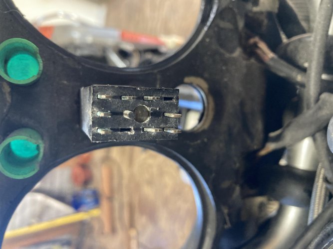
The 3 wires that were attached to my emergency flasher switch pulled loose while I was removing the cover to access my tachometer. There are lots of pins on the back of the switch. Where do thy attach?
And Merry Christmas. Hope yours was better than mine, I got Covid and spent the day in bed.

A4F4EA4A-5F89-44B7-8B97-BC1960B8DE4E.jpeg7087F9B1-7F47-42A2-A736-38916E058B0B.jpeg
 

Attachments

  • 67A8ADD1-84EC-476E-88A2-508B8E8D301F.jpg
    67A8ADD1-84EC-476E-88A2-508B8E8D301F.jpg
    253.4 KB · Views: 114
  • EE6A29C7-5493-4AA8-B48A-1F37F22B22FC.jpg
    EE6A29C7-5493-4AA8-B48A-1F37F22B22FC.jpg
    319.1 KB · Views: 117
I finally tracked down my BMW diagrams...a little hard to review on my computer screen. I found an 8-pole connector that says it's for the rev counter. For the pins shown, here are the colors that were connected:

1 - black [goes to headlight]
2 - gray/black [to speedometer lighting]
3 - brown/black [to starter relay]
4 - blue [to diode board]
5 - black (seems to go to the coil)
6 - green/blue [to plug on handlebar switch right]
7 - brown/green [to oil pressure switch]
8 - brown [appears to be ground]

Not my strong suit, but that's what I can make out.
thanks. what you supplied is info about the plug that goes to the tach. This model has the lights inside the tach as opposed to the ones on the pad. What I'm after is the three wires that were attached to my emergency flasher switch. confusing to me because there are so many unmarked pins. It's warming up today, so I'll get out to the shed with a meter and see if I can figure it out.
 
Wires

Jumping in late, I have the airhead hazard flashers on both of my bikes. I can say for certain, the three wires you have are not familiar to me. The system as in Snowbum's diagram has a dedicated plug for the back of the switch with more than three wires. wires were not just plugged individually into the back of the switch. There is a dedicated harness for the hazard lights. At least on the hazard system I am used to seeing.

The reason for the three wires is there is a internal LED in the switch itself that is dim when power is on and flashes bright when the flashers are on.

IF you don't have this switch with the internal LED, I am guessing your switch might be more in line with a K bike hazard switch. From what I recall, those switches do not have the internal LED.

As some K bike technology started to creep into the R bike lines the later part of the Airhead years, and with the GS and ST models being sort of oddballs from the other airhead models, It is possible a K hazard system was used on your bike.

LOL, sorry for any confusion. St.
no confusion. as I suspected from the previous schematic, the wire colors did not match and the wiring to the switch has been basterdized. In an emergency, I'll just frantically wave arms.
 
Pod

LOL, previous owner disease has affected your wiring.

I know it sounds snooty but I always advocate returning wiring back to OM as soon as possible. For what ever reason the PO wired the hazard switch the way he did, leaves you as the current owner with a possible ticking time bomb. Who is to say down the road the turn signals stop working and you find the bastardized wiring the PO did creates a nightmare trouble shooting the issue and or makes repairs a royal pain.

Now I don't know how the Hazard lights are configured in the wiring of your bike, I have no experience with the GS or ST bikes. I do know however in the other airheads, the factory wiring harness ties into the turn signal system with a diode and such.

I don't know how fussy you are, perhaps I am blowing hot air but I like things to work the way they are supposed to.

I believe the stock hazard wiring harness is still available. IF you want the hazard lights to work, I would suggest getting rid of the bogus wiring and installing the proper harness. If you don't care if the hazard lights work, I would take a bit of time to closely examine the stock wiring for the turn signals and eliminate the bogus wires. Down the road, you may be thankful you did.

Yeah,a lot of bull here, enjoy the riding. St.
 
How about…… I take it the emergency flashers worked before the tachometer cover was removed?

Try looking further back in the wiring to see where the wiring changes back to the original harness and mark the extensions. I doubt the previous owner(s) changed any wiring out of boredom.
It’s not black magic, its just time and investigation…….and some labeling tape so you don’t have to do this again.

OM
I don't know if they worked. I bought the bike as a non runner with no battery . the turn signals did not work properly until I took apart the flasher and de oxid it. I will investigat the wiring though. good advice, thanks.
 
When I run into this kinda deal and need a “plug” to keep it all straight, I usually can’t get the mating plug.

I will take the side that I have- such as this-

FD8AFB3C-0CCD-492E-A541-A902614605EA.png

And build a sort of “dam” around it using first the outside of duct tape facing in and then reinforce as needed. Once the connectors are paired up to where they are supposed to be, I fill the cavity I have created with hot-melt glue. When the glue hardens, the results are the plug I needed.
No doubt not as nice as OEM but pretty serviceable.

OM
 
Back
Top