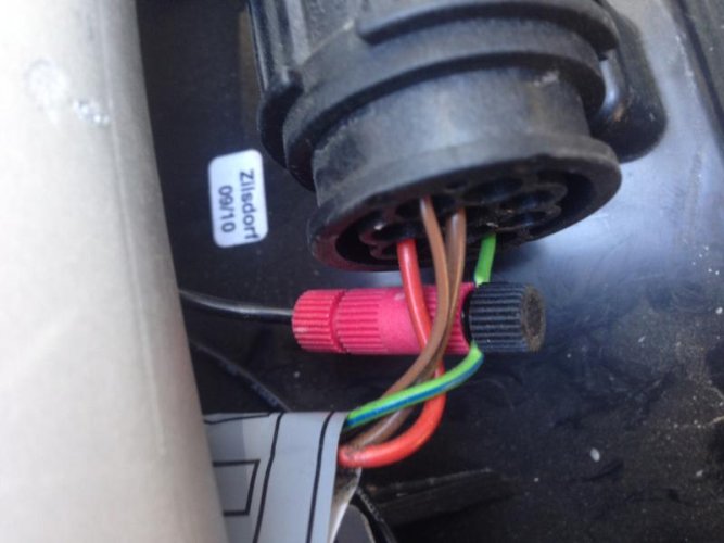
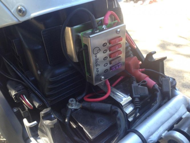
I recently purchased a new to me 2010 R1200GS and sold my '01 R1150 GS. Wanting to add a few things, I decided to add a fuze block, and went with the Centech AP-2 which offers several switched and a couple of unswitched circuits.
I purchased the kit for my bike from Excel Cycle Werks - http://www.excelcyclewerkes.com/index_files/Page672.htm to make the most of my limited mechanical skills by having the whole thing ready to go.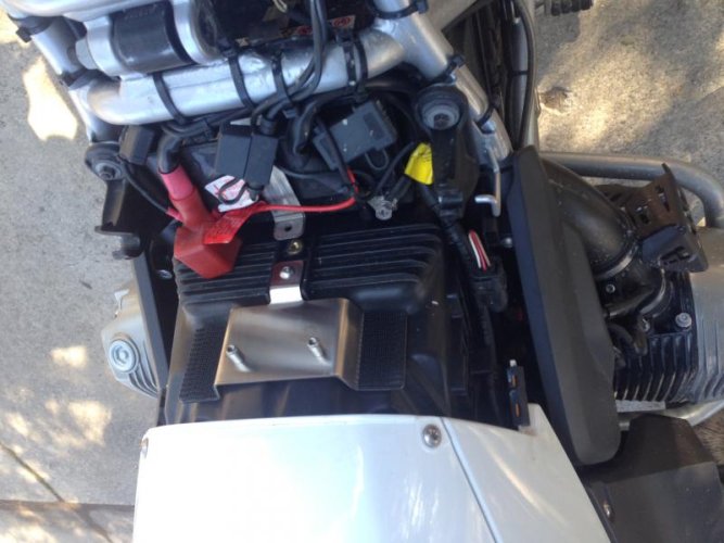
The kit includes a bracket, which takes the place of the T bracket that mounts to the body panels over the gas tank. You reused the clip nuts and existing bolts. I wasn't completely loving the resulting flex in the panels but after putting everything back together it seems ok. the bracket fits perfectly and feels very solid.
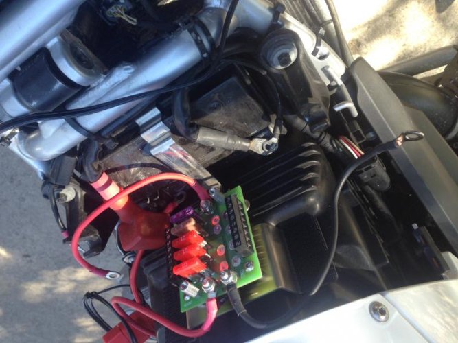
You mount the unit onto the bracket, and the wires and relay are all set to go. The only thing left to remove is the right side plastic side cover. I've learned to push them out by putting pressure on the rubber christmas tree vs. pulling them off.
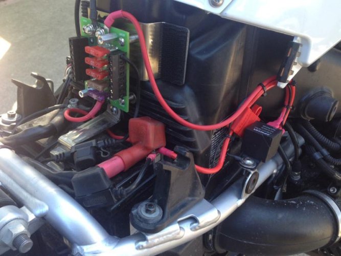
You connect the relay to an existing bracket (already threaded but unused), which is scraped to clean metal to insure a good circuit. electrical grease is provided in the kit to help maintain good connections as well.
The relay connects via a slick little power tap and after a few zip ties everything was ready to go. The relay worked perfectly and the whole thing went together well.
I'm at my three picture limit so will do a follow up post on the last connection and the fuze block installed.
Overall I was impressed by everything fitting well, wiring was long enough without extra to worry about and I like the simplicity of switched and unswitched options, as well as the 60amp relay capacity.
Tom at Excel Cycle Werks was friendly, shipped right away and everything came as promised.
I purchased the kit for my bike from Excel Cycle Werks - http://www.excelcyclewerkes.com/index_files/Page672.htm to make the most of my limited mechanical skills by having the whole thing ready to go.

The kit includes a bracket, which takes the place of the T bracket that mounts to the body panels over the gas tank. You reused the clip nuts and existing bolts. I wasn't completely loving the resulting flex in the panels but after putting everything back together it seems ok. the bracket fits perfectly and feels very solid.

You mount the unit onto the bracket, and the wires and relay are all set to go. The only thing left to remove is the right side plastic side cover. I've learned to push them out by putting pressure on the rubber christmas tree vs. pulling them off.

You connect the relay to an existing bracket (already threaded but unused), which is scraped to clean metal to insure a good circuit. electrical grease is provided in the kit to help maintain good connections as well.
The relay connects via a slick little power tap and after a few zip ties everything was ready to go. The relay worked perfectly and the whole thing went together well.
I'm at my three picture limit so will do a follow up post on the last connection and the fuze block installed.
Overall I was impressed by everything fitting well, wiring was long enough without extra to worry about and I like the simplicity of switched and unswitched options, as well as the 60amp relay capacity.
Tom at Excel Cycle Werks was friendly, shipped right away and everything came as promised.

