roger 04 rt
New member
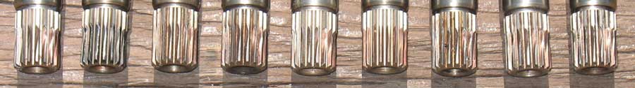
Input Shaft Photo from Anton Largiader
These pictures show the common pattern seen on the R1150 transmission input shafts when there has been excessive wear. Many possible causes and solutions have been identified and debated and there have been a couple good threads recently: Checking for spline wear 1999 R1100S, and tranny input shaft. Looking at the pattern of wear on the spline, which occurs inboard on the shaft and at an angle to the spline tooth, it can be hard to imagine how or why that exact shape develops. For months I've been thinking about a model for the wear pattern on the R1150 input shaft and feel that I've come up with one.
Many assert that misalignment is the ultimate root cause of wear. It is my view that misalignment gets the wear started and other problems cause it to accelerate. The key to the pattern of wear on the input shaft is that all misalignments, whether flatness of the clutch housing/flywheel or a shift of centerline between engine and transmission, result in an angular force on the clutch-hub which gets applied to the input shaft. (Since the transmission input shaft is in a separate assembly from the engine crankshaft, there will always be some misalignment, and it isn't known how much misalignment the R1150 can handle without excessive wear.)
The easiest way to imagine how misalignment leads to the angular force causing the wear that's observed is as follows:
Start with a perfectly aligned crankshaft/input shaft and then lower the transmission input shaft enough for a total tilt of 1 degree from the engine end of the clutch hub to the transmission end of the hub--about 0.017". Now imagine some play in the hub/spline coupling such that the tilt can actually happen. (This model also works if the clutch-housing/flywheel are tilted but wear progresses around the shaft/hub as clutch release/reengagement changes the hub-flywheel rotary position. Also, I am only using a downward shift as that is easier to explain. Any shift yields the same results.)
With the transmission lowered by a degree, viewed from the rear:
--the clutch-hub splines in the 12 o'clock position are up at the engine end.
--the hub splines at the 6 o'clock position are down at the transmission end.
--the clutch-hub splines at 9 o'clock position press on the input shaft only at the end near the transmission and are up off the input shaft at the engine end.
--and the hub splines at the 3 o'clock position contact the input shaft only at the engine end and are down and off the input shaft at the transmission end.
These differing contact points lead to wear since there is extra pressure (pounds per square inch) and the surfaces change continuously as the shaft turns.
The "give" in this system, is the sheet metal web that holds the clutch-hub to the disc. As the engine rotates, the contact points change position such that in the y-axis (12-6 o'clock) the splines are rocking up and down, end to end as the shaft turns. And in the x-axis the clutch-hub contact point moves from the engine end of the transmission spline, to the transmission end as it rotates. (And also, based on an amount equal to [1-cosine{misalignment angle}] there would be a tiny in/out motion along the transmission shaft.)
This pattern of contact would vary continuously as the clutch-hub rotates (in a sort of figure 8 pattern) with the teeth sliding on one another at high pressure. Further, under hard acceleration, it is possible the forces are great enough that the 9/3 o'clock positions might flatten against the shaft, meaning more motion under even higher pressure. Whether that happens or not, the contact area on the splines, and hence the pressure would get very high as they pass through the 9/3 o'clock positions. That high pressure in the model is what I'm postulating leads to the wear.
There's another factor that may speed wear once it has begun. The engine produces its torque for only about 1/3 of its rotation. That means that the torque during the 1/3 period is on average 3X the torque reaching the rear wheel. Peak torque within the 1/3 period would be even higher. The damping of these peaks doesn't happen before the hub-spline engagement, it happens in the transmission. Whether this plays a role in acceleration of the wear is a question.
What might improve things? Better flywheel/clutch housing flatness, better crankshaft to input shaft alignment, harder materials, lasting lubrication, longer hub/spline engagement to effectively tighten the coupling and limit the range of motion. It seems each situation will be different.
I plan to measure flywheel flatness, lubricate and possibly extend the clutch hub, all depending on what I see when I open it up, I'm at 30,000 miles.
RB
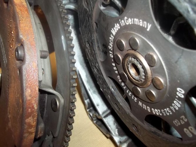
Damper photo from GSAddict
Last edited: