• Welcome, Guest! We hope you enjoy the excellent technical knowledge, event information and discussions that the BMW MOA forum provides. Some forum content will be hidden from you if you remain logged out. If you want to view all content, please click the 'Log in' button above and enter your BMW MOA username and password.

    If you are not an MOA member, why not take the time to join the club, so you can enjoy posting on the forum, the BMW Owners News magazine, and all of the discounts and benefits the BMW MOA offers?

  • Beginning April 1st, and running through April 30th, there is a new 2024 BMW MOA Election discussion area within The Club section of the forum. Within this forum area is also a sticky post that provides the ground rules for participating in the Election forum area. Also, the candidates statements are provided. Please read before joining the conversation, because the rules are very specific to maintain civility.

    The Election forum is here: Election Forum

Some Electrical System Documentation for /5 Series Bikes

brook.reams

B Reams
Folks,

I put together a series of documents about BMW airhead motorcycle electrical systems. It strikes me that electricity in general, and motorcycle electrics in particular, are dark mysteries to many, so I thought I'd shine some light [puns intended :) ].

Lack of understanding hinders confidence when diagnosing and working on electrical projects. As these bikes age, the electrical system is prone to problems as corrosion and neglect makes them behave badly. More owners are having more electrical problems but seem less able to get to the root cause of the problem.

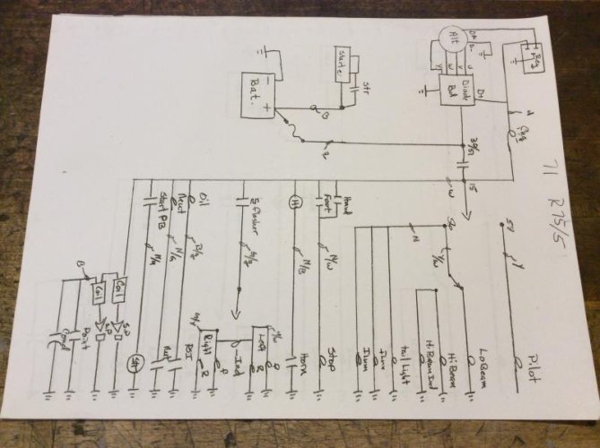
I think one tool that many avoid using is the wiring diagram. The spaghetti of lines, symbols and notations makes the eyes glaze over. "Oh goodness, where do I start?" is the common response to the advice, "Look at the wiring diagram."

WiringDiag_5 Series_1969-1973.jpg

5 Series Wiring Diagram (1970-1973) (Source: Haynes Manual)

I'm not an electrical engineer, but I have taken time to learn the basics, have collected comments and input from well respected airhead mechanics and dug into how BMW applied electrical theory when they designed the /5 electrical system. I've learned a lot from various reference sources that are scattered about the internet, so my articles include a bibliography of various useful resources. That way both you and I have a nice set of reference materials to consult when problems come up.

I have published three articles (so far), Basics and two others about the /5 series: 5 Series Circuits and, 5 Series Electrical Components. I chose the /5 series to start with because I believe it's the most popular airhead series for restoration.

Here are links to the documents which also appear on the index on the right side of the blog pages.


I hope to write an Electrical Circuits and Electrical Components document for the /6 and /7 series up to 1984.

I hope this is helpful.
 
Brook -

Will your efforts highlight errors and omissions from the various publications? It's no secret that these diagrams contain errors and problems. With all your work restoring bikes, have you gone through and verified the diagrams you've worked with?

There are many sources for diagrams. One that I don't look at very often but probably should are the ones published by the Chicago Technical or ChiTech organization. If I'm not mistaken, Oak was involved in them. Plus I believe Snowbum has errata sheets for the diagrams.

Kurt,

You point out part of the "fun" of airhead electrical systems: reliable wiring diagrams. Although the graphics are based on the ones in the Haynes manual, I cross referenced the diagrams in the CHITECH electrical training manual. It's in the list of resources I published in each of the documents so readers can, if the wish, go to my source material. That said, I found minor errors in the CHITECH diagrams, and starting at about the /6 series, many of the details are illegible due to poor reproduction from the original drawings. That's frustrating, but I can't fix their publication.

As you mention, Oak was the primary contributor to the CHITECH training material. Bob Fleischer, aka Snowbum, also published his corrections to the original manual, which I list in my Resources. Again, even the best intended authors quibble over interpretations of electrical design details.

To answer your question did I ".. highlight errors and omissions from the various publications?" No. I can't control other author's corrections nor do I want to impune their material. Instead, what I wrote is correct as best I know. That said, I welcome any input on errors I made. Unlike a hard copy manual, I will correct them and note that in the "Revisions" section that will be added when I receive a correction.

The one thing I really wanted to bring into focus with these documents is the method I use to explain the circuits. I draw each circuit leaving out the unnecessary wires. My hope is the simplification of the diagram with step-wise construction of each circuit makes it easier to understand each of them. Combined with the "Electrical Components" document, which explains how I understand each electrical component works, this should help people get a better understanding of the electrical system.

I hope that helps. I helped me learn and understand the /5 electrical system much better than I did when I rebuilt my R75/5 :)

Best.
Brook.
 
The one thing I really wanted to bring into focus with these documents is the method I use to explain the circuits. I draw each circuit leaving out the unnecessary wires.

5-Series-High-Beam-Flasher.jpg


As an example, this is what I was thinking I was going to see when I opened the link. When you publish your book these pages should be on transparent stock so they can be overlaid with each other. Conductor sizes would be helpful information, but certainly not critical to understanding the circuit(s).

Again Mr. Reams... :bow

Hi Lew,

I have no plans to "...publish a book...", too 20th century. :)

I did not plan to replace the many existing wiring diagrams, of which there are multiple sources, all of which include wire sizes. I recommend anyone working on the electrical system get one, or more, versions of the wiring diagram for their bike.

What I wanted to do was cut away the clutter of the entire diagram to zoom in on the relevant wires for particular circuits. I think that helps comprehension and understanding so folks build confidence they can tackle issues with their wiring system.

Perhaps it's best to think of these documents as "supplements" or "tutorials" that assist folks in building their comprehension of /5 wiring systems. That was why I collected the content over time: to assist me in comprehending it.

I drew the wiring diagrams as overlays using Apache OpenOffice Draw. I think there are about 30 layers in the master drawing. That turned out to be a flexible way to segment the complete diagram so I could selectively combine parts of various circuits and only display the overlays I needed. This provided great flexibility in developing the final publication as I experimented with what seemed the best way to show the diagrams.

The icons from the Hayne's manual were cut out as individual jpeg files and cleaned up. My original plan was to construct the diagrams from individual icons. As I went down that road, it became clear the easier method was to keep the full diagram with all the icons, erase the wires, then add them back in by hand using layers to organize the wires by circuits.

More than you wanted to know, I'm sure :)

Best.
Brook Reams.
 
There are wiring diagrams and schematics. Schematics are easier for me to understand, however they do not represent the path of the wire(s). I build my own wiring harnesses on every bike I build. The stock /5 harness is a pretty good layout. I did make some minor changes. I use 1 fuse, and moved it under the seat, basically everything else is fine. I use ladder schematics, just because they are what I worked from for many years in the petro/chemical industry. The wiring diagram brook posted from the Haynes manual uses a layout that indicates the location of the devices. My crude hand drawn ladder schematic shows how it works. I did not show a detail of the rectifier.
 

Attachments

  • image.jpg
    image.jpg
    55.7 KB · Views: 50
Last edited:
There are wiring diagrams and schematics. Schematics are easier for me to understand, however they do not represent the path of the wire(s). I build my own wiring harnesses on every bike I build. The stock /5 harness is a pretty good layout. I did make some minor changes. I use 1 fuse, and moved it under the seat, basically everything else is fine. I use ladder schematics, just because they are what I worked from for many years in the petro/chemical industry. The wiring diagram brook posted from the Haynes manual uses a layout that indicates the location of the devices. My crude hand drawn ladder schematic shows how it works. I did not show a detail of the rectifier.

10drum,

It's funny you should mention use of ladder schematics. I considered that when I was planning this project. In the end, I thought it might be more useful to stay with a commonly found wiring diagram and then build each circuit on top of the background component template using overlays.

I often make sketches of parts of a diagram to help me focus on the area that I think is the likely source of a problem. As Einstein said, "One should make things as simple as possible, but no simpler." :)

You also make a good point about the value of more than one representation of things, a logical and a physical diagram for instance, to help someone understand complex things.

Best.
Brook.
 
Back
Top