•  

    Welcome! You are currently logged out of the forum. Some forum content will be hidden from you if you remain logged out. If you want to view all content, please LOG IN!

    If you are not an MOA member, why not take the time to join the club, so you can enjoy posting on the forum, the BMW Owners News magazine, and all of the benefits of membership? If you click here, you have the opportunity to take us for a test ride at our expense. Enter the code 'FORUM25' in the activation code box to try the first year of the MOA on us!


Mysterious Blowing Fuse ‘78 R100/7

sonny_p

New member
Hey, everybody! Looking for some sage wisdom to help with a mysterious blowing fuse that I have on my 1978 BMW R100/7.

Here’s the full story:
Went on a ride two weeks ago and somewhere along the way lost several electrical systems at once: all 4 turn signal lights, brake light, turn signal indicator light and buzzer, and voltmeter. Quick google told me that these systems are on the same 8A fuse in the headlight bucket wiring assembly. Went to explore inside the headlight bucket and discovered the fuse had in fact blown. I had six spare 8A ceramic fuses from a local BMW Motorad shop, and threw a new one in. Turned the ignition on, and the fuse did NOT blow. Watched the fuse as I tested turn signals and brake light. All systems seemed normal. My first thought was that I couldn’t have a short, or else the fuse would have blown immediately with the ignition turned on, right? I waited and watched and kept testing systems and the fuse seemed happy, so threw the headlight back on and went to ride again. Sure enough, only took 50 yards for the fuse to blow. Now I began to wonder if maybe the shaking of the engine pinched a cable to cause a short that I couldn’t locate with the bike sitting still. Went back behind the headlight and came to the forum to see if others had seen this before. A few folks seemed to have similar symptoms that were caused by a faulty turn signal relay. I pulled out my multimeter and tested resistance across each prong of the relay to make sure I didn’t have an internal short inside. Resistance tested normal, so I went to test voltage. The relay was getting a normal 12V’s of power. And with a new fuse in place, the appropriate relay prongs for the turn signals flashed 12V intermittently with the lights. It seems that the voltage and resistance across the relay is normal. Testing each of the systems again, the new fuse did not blow. I figured it must be some sort of draw that only happened when the engine was on (which was wrong). Fired up the engine and had a friend peek inside the headlight bucket. All systems still worked normally! BUT THEN I tried something new—front brake lever AND turn signal. The fuse blew. Well, that explains why the first time I tried to fix it I only made it 50 yards—that’s the first time I first squeezed the brake and put on my turn signal!

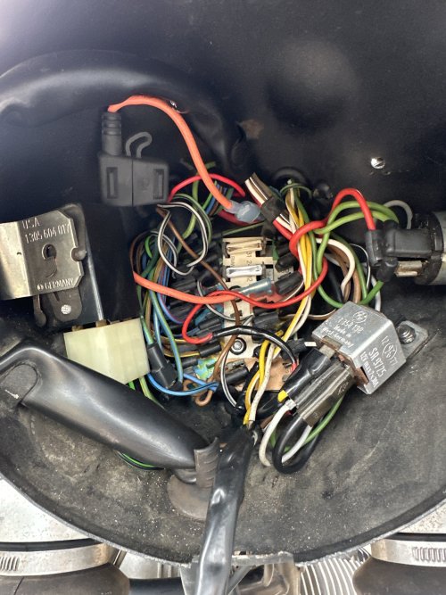
So that’s the long exposition. Here’s the TLDR—after two blown fuses, I’ve figured out that the combined current draw of my brake light and turn signal lights is greater than 8A. The bike seems pretty damn stock to me (though I’ll readily admit to being a newbie airhead!) so I don’t think that’s the issue. There are maaayyybe one or two electrical parts in the headlight bucket that seem aftermarket. But before this issue, the bike worked normally for thousands of miles. No recent new changes. Included a pic below of my headlight electrical assembly.

Thanks for the help brainstorming on this one!
 

Attachments

  • IMG_8F4B2220-9D12-4D3E-85B2-73F80F27D716.jpeg
    IMG_8F4B2220-9D12-4D3E-85B2-73F80F27D716.jpeg
    1 MB · Views: 16
Can you measure the current across this fuse and then use the turn signal, then use the brake light, then do both at the same time. Do you see changes in the amperage?
 
OK, I’ll go to bat first !
The mini-spade fuse with holder is aftermarket ! It is pulling positive power from the main power location on the circuit board; where is the output from that mini-spade fuse going… aftermarket accessory ?
There is an obvious repair (electrical tape) on the smaller gauge red wire by the headlight relay, which is unfused.
The turn signal relay is electro-mechanical; the interior slave points driving the magnetic coil switching the master relay power corrode and often stick or, draw too much current. Highly recommended you remove that electro-mechanical relay and install an electronic relay !
When was the last time you performed a “stem to stern” disassemble/clean/anti-corrosive compound/reassemble of ALL the spade connections, bulb sockets, grounds on this forty seven (47) year old Motorrad ?
The main wiring loom passing from the main frame into the headlight nacelle, fatigues the outer sheath as well as the individual wires inside it, from all the handlebar turning. Further back, the fuel tank often wears upon the loom running alongside the frame’s “backbone” which presses circuits together to short.
Take a look inside each turn signal pod and rear light nacelle as most of their connections are “wire pinch” type; follow-up with a careful inspection of the multi-pin connector for them, on the left-hand, rear main frame down tube, near battery… nasty place for dust/road wash to accumulate !
If I get a chance, I’ll pull out a /7 wiring plan and try to identify that “wounded” red wire…
 
Can you measure the current across this fuse and then use the turn signal, then use the brake light, then do both at the same time. Do you see changes in the amperage?
This is a solid next step, shoulda thought of that! that should tell me which component is drawing more than its fair share. Update to come 🫡
 
OK, I’ll go to bat first !
The mini-spade fuse with holder is aftermarket ! It is pulling positive power from the main power location on the circuit board; where is the output from that mini-spade fuse going… aftermarket accessory ?
There is an obvious repair (electrical tape) on the smaller gauge red wire by the headlight relay, which is unfused.
The turn signal relay is electro-mechanical; the interior slave points driving the magnetic coil switching the master relay power corrode and often stick or, draw too much current. Highly recommended you remove that electro-mechanical relay and install an electronic relay !
When was the last time you performed a “stem to stern” disassemble/clean/anti-corrosive compound/reassemble of ALL the spade connections, bulb sockets, grounds on this forty seven (47) year old Motorrad ?
The main wiring loom passing from the main frame into the headlight nacelle, fatigues the outer sheath as well as the individual wires inside it, from all the handlebar turning. Further back, the fuel tank often wears upon the loom running alongside the frame’s “backbone” which presses circuits together to short.
Take a look inside each turn signal pod and rear light nacelle as most of their connections are “wire pinch” type; follow-up with a careful inspection of the multi-pin connector for them, on the left-hand, rear main frame down tube, near battery… nasty place for dust/road wash to accumulate !
If I get a chance, I’ll pull out a /7 wiring plan and try to identify that “wounded” red wire…
I didn’t know that about the relay internals! Any suggestions for a worthy replacement electronic relay that removes the chance for mechanical failure?

Admittedly, I have not done a forward to aft electrical dissection. I’ve owned the bike (my first airhead!) for just under a year, so I’m still learning so much about these machines. I’ve done maintenance on carbs, tank lining, brakes, valves, oil system, fluids, etc., but the electrical system has been an intimidating next step that I haven’t yet taken! This is just the nudge I needed to make it happen.

The electrical tape scared me at first too! Fortunately I’m in touch with the previous owner (my older neighbor who has since stopped riding) and so I was able to ask him about that. He said it was a past repair from an accident pinching that wire’s insulation against the sharp metal edge of the headlight relay when pushing on the headlight trying to seat it. He told me it didn’t cause a melting short, but that the wire’s insulation looked sliced, hence the tape. I also noticed that aftermarket fuse connector! I asked him about that and he had no idea 😅. I can’t think of any obvious aftermarket electrical components that it might connect to! I’ve not ridden any other airheads to compare it to, but it seems mechanically/electrically stock as far as I can tell. Nothing extra at all on the instrument cluster.

I’ll be back in the garage tonight and inspect those spots you mentioned! All sound like great potential inspection points. I’m also going to check current across the fuse as I operate each individual component so I can figure out which system is drawing more than its fair share! More updates to come. Thanks for the advice!IMG_2946.jpeg
 
As you said, there are other items on that circuit. Probably need to get some data on each one in terms of what it adds to the current draw.
 
there’s some diagnostic info missing here. When you installed the new fuse and tested lights, did you use the rear brake to activate the brake light, the front brake, or both? And the same question after the fuse blew 50ft into the test ride: rear brake, front brake, or both? And last, did you try a test rider using only the rear brake? It gets to the question of whether it’s an issue with one brake or the other, or with the brake light circuit itself. I always like to do the simple tests first, in hopes of narrowing the area(s) needing attention, before breaking out the electrical tools or considering wholesale changes to the system.
Just a thought.

Best,
DeVern
Good call! The first test ride I didn’t realize that it was a combination of turn signal and brake, so I didn’t take note of which brake I used. Only discovered that it was a combination issue when I tested them at the same time at stand-still. On the second fuse test it was the front brake lever and the left turn signal. BUT I tested front brake with turn signal *before* I had the chance to test rear brake with turn signal, so theoretically I have not ruled out that the brake light is faulty from either lever. Neither brake individually blew the fuse. 🤔
 
Perhaps "measure the current across the fuse" needs to be re-stated: a fuse is essentially a short in and of itself, so the current "across" it would be minuscule.

Current is measured in series (typically), so you would need an ammeter that can safely read 10 amps.
One may pull the fuse and insert the ammeter probes into the socket contacts ("red" goes to the current/voltage source, "black" to the load - especially important if it's an analog meter because you don't want to "pin" it backwards), but then the only "fusing" you have is inside the ammeter, and if that's appreciably high, you may end up with a melted component downstream. ⚡

Jury-rig (aka kludge) a way to have both the stock fuse in place, in series with the ammeter also in that line.

Oliron brings up several good points - it may be as simple (although frustrating to locate) as a shorted bulb (where, when the filament broke, its support arms bent inward toward each other) or its socket.
Just hooked up my multimeter to the fuse prongs and did some current reads! Got some odd results. The first readings were seeming normal, until I used the left turn signal and front brake lever, which actually blew the 10A fuse inside my multimeter. I wanted to replicate results and check to see if the rear brake combination would do the same, so I reset and went to test again. The second test produced these results:

Right turn signal 4.98
Left turn signal 5.04
Front break lever 2.05
Rear brake lever.2.53
Front brake with right turn signal. 5.6
Front break with left hand signal. 5.6
Foot break with right turn signal. 5.6
Foot break with left hand signal 5.6

All seems normal, nothing drawing more than 8A. Seems my problem may be an intermittent arcing short? Possibly inside a brake or turn signal bulb? Or inside the turn signal relay?
 
… I recommend that you substitute the electro-mechanical turn signal relay with an electronic one. Many times, I’ve found that the OEM ones in the aluminum cans (/5s), square plastic box (/6 &/7), become troublesome with age; internal resistance rises causing more current draw especially at low system voltage: 12 - 13VDC.

“Frugal” ‘Hedz often replace the /5 OEM relay with those very small thermostatic relays ( 1/2” x 3/4” x 1” metal cover); they stall below 12VDC and need 14+ VDC to give a reasonable blink rate…


IMG_7310.jpeg

This is the electronic relay for /5s…

IMG_7050.jpeg

Take your existing turn signal relay (electro-mechanical /6 & /7) to a FLAPS* ; find an electronic unit with similar spade arrangement, they’ll work consistently down to 9VDC and, no internal moving parts. The current BMW pricing for the 61 31 1 358 194 relay is… $120+ !

IMG_7309.jpeg

So much so for “Keeping It Simple” ?

“Plug & Play” and check results**

* Friendly Local Auto Parts Store
** We’re talking BRAKES here while looking for BREAKS in the electrical system 😉
 
Last edited:
If you have the "typical" 1156 bulbs in the turn signals, they pull about 2.1 to 2.3 amps each, so your measurements are pretty reasonable.

If you are still using the original relay, this is one case where "throwing parts at it" is not unreasonable - R&R it.
A typical modern relay is about $20 to $30 at your FLAPS (and BMW's is blatant robbery!).

The turn signals and brake/tail light assembly are pretty easy to completely disassemble on the bike (you may need new gaskets in the turn sigs if they're original too); look for issues on the bulbs' bases, in the sockets, and where the wiring connects to the sockets.

While you're in there - if you'd like to convert to LEDs (or even if not), Cyclops has a flasher here:
 
Last edited:
Back
Top