• Welcome, Guest! We hope you enjoy the excellent technical knowledge, event information and discussions that the BMW MOA forum provides. Some forum content will be hidden from you if you remain logged out. If you want to view all content, please click the 'Log in' button above and enter your BMW MOA username and password.

    If you are not an MOA member, why not take the time to join the club, so you can enjoy posting on the forum, the BMW Owners News magazine, and all of the discounts and benefits the BMW MOA offers?

1980 R100T Coil Wiring Question

nevadaslim

New member
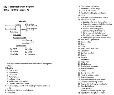
I've replaced the badly deteriorated main wiring harness on my 1980 R100T.

I have some questions as to how the ignition coil wires should be hooked-up.

A while back I found by accident an excellent drawing of the coils from the front perspective.
It showed the wire colors and the polarity of the terminals on the coils. Unfortunately after hours
of doing web-searches I'm unable to find it again. An opportunity-missed!

Below is a drawing I made, the way I think the coil wires should be hooked-up. Is it correct?
Coil Wiring Drawing.jpg
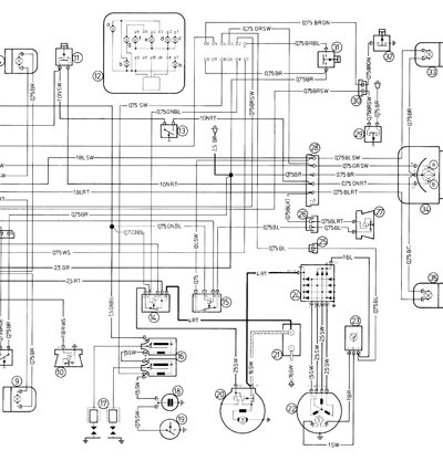
Anyway, I've got schematics from:
* Clymer
* Haynes
* BMW Rider's Handbook
* BMW Repair Manual R60/7 - R100 RS

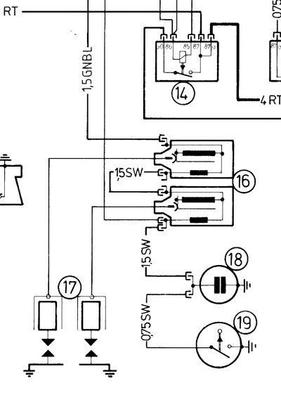
They all show how the coils are hooked-up, but none give the polarity of the wires on the coils.

And I also need to know how many wires should be actually hooked-up to the coils? As best as
I can tell, only three. A green, black, and short jumper. Is that correct?

After hours of research w/o any luck, I would appreciate any help, exhausted!!!
Mike...

Note: If anyone knows where on the internet the drawing is that looks like mine, please post the link.
 
Last edited:
That is the only way it can be hooked up. Power into one coil, out through the jumper to the other coil, then out of the second coil to the points/condenser. There should be another small black wire out of the second coil that leads to the tachometer...this gives you RPMs.

I don't recall seeing the diagram you mentioned. But Duane Ausherman has a few diagrams on this webpage:

http://www.w6rec.com/duane/bmw/points/index.htm

As I said, you still need the wire for the electronic tach.
 
This may help, or not.

These are diagrams from the BMW factory repair manual for a 78 R100S. I can only assume that they are the same. Maybe they will help. I can provide the full diagram if you need it, but I think the right side shows you what you need. There was no mention in the manual of polarity. If needed, PM me and I can scan and email you a better copy of the files, including the rest of the diagram.
 

Attachments

  • What things are.jpg
    What things are.jpg
    77.1 KB · Views: 76
  • Coil only.jpg
    Coil only.jpg
    81 KB · Views: 75
  • Coil and other wiring.jpg
    Coil and other wiring.jpg
    95.9 KB · Views: 78
That is the only way it can be hooked up. Power into one coil, out through the jumper to the other coil, then out of the second coil to the points/condenser. There should be another small black wire out of the second coil that leads to the tachometer...this gives you RPMs.

I don't recall seeing the diagram you mentioned. But Duane Ausherman has a few diagrams on this webpage:

http://www.w6rec.com/duane/bmw/points/index.htm

As I said, you still need the wire for the electronic tach.


Thanks for the confirmation,

I thought there was at least another wire to hook-up. The Haynes drawing doesn't show the tach wire, but now you mention it the Clymers does. I'll have to look for it when I get off work today.

Mike...
 
Last edited:
These are diagrams from the BMW factory repair manual for a 78 R100S. I can only assume that they are the same. Maybe they will help. I can provide the full diagram if you need it, but I think the right side shows you what you need. There was no mention in the manual of polarity. If needed, PM me and I can scan and email you a better copy of the files, including the rest of the diagram.


Thanks for the reply toooldtcare.

Have have these drawings but unfortunately they don't show the polarity on the coils. That's what I needed, the (+) & (-)'s.
What wire goes where. But I got it now.

Mike...
 
I am typing from an iPad, so I do not want to redo this, read my whole answer before doing anything.

Look at the diagram showing the coils. One wire from one coil goes to the points, the other coil has a wire going to the main harness. The one going to the points is negative since it conducts the signal to ground.

Looking at the diagram more you see that the positive of that coil goes to the negative of the next coil. The positive of that coil goes to the main harness.

Now to determine which is which you can use a VOM (volt-ohm meter). With the key off, set the meter to read resistance and connect it to one of the wires in question. If it reads continuity, good. Leave it there and rotate the engine by turning the rear wheel with it in 5th gear. Watch the meter. If it is the points wire it will go open, then closed again, that is the points wire, also the negative wire.

Or, the second way is to turn on the key and and set the meter to read volts. One of the wires will have 12 volts on it, the other zero. The one with the 12 volts is the positive wire.

Question, are the coils marked + and -? If not than it does not matter much, but I bet they are.

Also, the green black is the positive, the black negative. Should have though of that before.

Edit, read this. http://mgaguru.com/mgtech/ignition/ig104.htm

If the coils are not marked, you may want to do this.

Wayne
 
Last edited:
I am typing from an iPad, so I do not want to redo this, read my whole answer before doing anything.

Look at the diagram showing the coils. One wire from one coil goes to the points, the other coil has a wire going to the main harness. The one going to the points is negative since it conducts the signal to ground.

Looking at the diagram more you see that the positive of that coil goes to the negative of the next coil. The positive of that coil goes to the main harness.

Now to determine which is which you can use a VOM (volt-ohm meter). With the key off, set the meter to read resistance and connect it to one of the wires in question. If it reads continuity, good. Leave it there and rotate the engine by turning the rear wheel with it in 5th gear. Watch the meter. If it is the points wire it will go open, then closed again, that is the points wire, also the negative wire.

Or, the second way is to turn on the key and and set the meter to read volts. One of the wires will have 12 volts on it, the other zero. The one with the 12 volts is the positive wire.

Question, are the coils marked + and -? If not than it does not matter much, but I bet they are.

Also, the green black is the positive, the black negative. Should have though of that before.

Edit, read this. http://mgaguru.com/mgtech/ignition/ig104.htm

If the coils are not marked, you may want to do this.

Wayne


Thanks Wayne,

Yes, the coils are marked (+) & (-). If you zoom in on my photo you can see both of the (+)'s, it's to hard to see the (-) signs.
So as it stands, from your feedback and others I've received I think my drawing is correct and I'll go with it.

After hooking-up the coils I still have to hook-up and adjust my choke and throttle cables to test the engine. Getting closer...
 
Back
Top