• Welcome, Guest! We hope you enjoy the excellent technical knowledge, event information and discussions that the BMW MOA forum provides. Some forum content will be hidden from you if you remain logged out. If you want to view all content, please click the 'Log in' button above and enter your BMW MOA username and password.

    If you are not an MOA member, why not take the time to join the club, so you can enjoy posting on the forum, the BMW Owners News magazine, and all of the discounts and benefits the BMW MOA offers?

  • Beginning April 1st, and running through April 30th, there is a new 2024 BMW MOA Election discussion area within The Club section of the forum. Within this forum area is also a sticky post that provides the ground rules for participating in the Election forum area. Also, the candidates statements are provided. Please read before joining the conversation, because the rules are very specific to maintain civility.

    The Election forum is here: Election Forum

Lights not working - no, it's not the bulbs :)

mmorgenroth

New member
On my 1991 R100GS the horn, indicators and all lights don't work with the key in the ON position while break lights do work.

In the park position the lights work. All fuses seem ok, too.

Any ideas?
 
When you say the fuses seem OK, what do you mean? Did you take them out and measure the tip to tip resistance? According to the diagram, the F4 fuse seems to be a common power source for those items. Does the clock work? It also seems to be on the same power circuit. Maybe try spinning the fuse and help scrape off any corrosion on the ends.
 
Yes, the fuses have continuity as measured with an Ohm meter And I sanded contacts and applied dielectric grease before reinstallation.

Also worth mentioning that the lights stopped working without any modifications, just stopped one day then worked again for a few days then stopped altogether.
 
Hmmm. I'm not so good with these diagrams, but now that I reread the key in the ON position, it does appear that one of the paths through the switch sends power to the load shedding relay. From there, power goes to the F4 fuse, which as I said before, appears to power those devices that don't work. I'm not sure what the internals are like on the relay, but it has terminals 30, 85, 86, and 87. Maybe check the connections on this relay?
 
On my /7, all of these relays are under the tank. Not sure about the '91. Maybe someone who's been there will drop in. These relays are cube about one inch on a side. They could be under the tank...could be inside the headlight shell. If you find these relays, you should at a minimum pull them out and replug them a few times. They are male terminals plugging into a base. The load shed relay, according to the diagram, has wires going to it that are red, black, green, and green/black.
 
"load shedding" relay? Whats that Kurt?

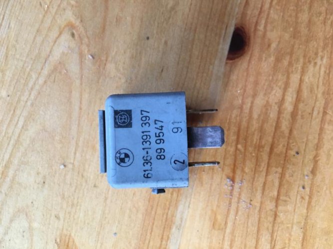
You speak of one like this?

Keep in mind that a relay needs a ground terminal (85) for the trigger circuit (86) ... so, as mentioned, check your ground connections/paths. If the relay doesn't make an audible "click" when energized it's dead (or not grounded).
beuler-bu-508td-time-delay-relay-02.jpg


Is this the diagram you're referencing? http://i864.photobucket.com/albums/ab208/batoutoflahonda/wiring.jpg
 
Kurt, I don't recall if our /7's did this or not, I know that the /5's that Lew and I ride are not so equipped, but the load shedding relay turns off accessory circuits (headlight,etc.) when the electric start is engaged. This is to allow for maximum current availability when turning the electric start motor. My knowledge and memory are a bit sketchy on this, but it seems to me any airhead without a headlight off option on the hi-lo switch might or ought to have a load shedding relay. To follow this notion out a few turns, the load shedding function might be incorporated in to the starter relay or associated with the starter relay if it is a stand alone component. I hope Paul Glaves sees this and issues commentary. I am confident that he would know all about it.
 
James -

My /7 does turn off the headlight when the starter is cranked. My Haynes doesn't show a load shed relay on the diagram, so it must be done somewhere else. The Haynes diagram for the '91 clearly shows the relay as part of the circuit routing out of the ignition switch. I'm just looking at the obvious...it could be more complicated than this. Certainly, making sure all relay contacts are free of corrosion and all grounds are solid is a first step.
I completely agree with your recommended first step. The question to my mind would be how mmorgenroth's non-working circuits line up with the circuits that are disrupted by the load shedding relay. For example, the flash to pass feature is wired hot thru the thumb switch on most airheads. On my /5, the flash to pass will light up with the key removed. The the horn is also hot thru the switch (not on a relay). The challenge here would be to parse the various functions by close scrutiny of the wiring diagram. Wiring diagrams give me headaches. I admire you and some of our other participants who try to analyze them for our friends here.
 
Wiring diagrams give me headaches.

Pass the aspirin! I just saw that the items that don't work seem to be connected to one particular fuse, but he says the fuse is good. Between that fuse and the ignition switch is really only one thing...the load shed relay. Simplistic, but seems like something to consider! :dunno
 
Let me echo the comment on headache about wiring diagrams and the generous feedback from the community ... thanks again for all your suggestions.

The relay needs to travel from Germany to Canada and will take a couple of weeks to arrive ... I will let you know if it was the culprit.

Of course it would be great if anybody knows a place that has it in stock here.
 
If we're still talking about the load shed relay, I believe that BMW part number is 61311459677. Some info I've squirreled away indicates that Bosch relays 0332017100, 0332207100, 0332207300, 0332207301, and 0332207310 might be possible replacements. Also, I wonder if such a relay was used on BMW cars??
 
5 terminals.

md_eac5c30c-f16c-4479-affb-c02b64aa115f.jpg


https://www.eeuroparts.com/Parts/68...MI8azVv4SU1QIVD7jACh2vKAwTEAQYAyABEgI2XPD_BwE

or almost any auto part store. Some have molded on mounting tab (easy to cut off)

Diagramatrically... is that a real word?

Anyway, here's what you get;

85 or 86 are the "trigger" terminals. One of them is hot (let's say 85), the other is grounded, machts nicht which one, power on/off operates a tiny magnet in the relay
30 is the power source you are directing
87 is powered until the current is removed from 85 (or interrupting the ground wire)
at which point the power is directed over to 87a.
One of the other is always "on". To kill both 87 and 87a you interrupt power to 30

The four terminal version operates exactly the same, except without 87a, it functions only as a simple on/off switch.

relay.jpg


eidt -Bosch relay 61361391397 is described as a "diode starter relay".
 
The new relay arrived, I plugged it in and ... nothing. The problem is still there.

So I tried a few other things but haven't solved the problem, yet. For example bringing 12 V directly from the battery via jumper cable to the fuse terminal gets all lights, indicator and horn working except the tail light ... but the tail light works on the parking position of the keyed main switch.
 
5 terminals.

md_eac5c30c-f16c-4479-affb-c02b64aa115f.jpg


https://www.eeuroparts.com/Parts/68...MI8azVv4SU1QIVD7jACh2vKAwTEAQYAyABEgI2XPD_BwE

or almost any auto part store. Some have molded on mounting tab (easy to cut off)

Diagramatrically... is that a real word?

Anyway, here's what you get;

85 or 86 are the "trigger" terminals. One of them is hot (let's say 85), the other is grounded, machts nicht which one, power on/off operates a tiny magnet in the relay
30 is the power source you are directing
87 is powered until the current is removed from 85 (or interrupting the ground wire)
at which point the power is directed over to 87a.
One of the other is always "on". To kill both 87 and 87a you interrupt power to 30

The four terminal version operates exactly the same, except without 87a, it functions only as a simple on/off switch.

relay.jpg


eidt -Bosch relay 61361391397 is described as a "diode starter relay".

The new relay arrived, I plugged it in and ... nothing. The problem is still there.

So I tried a few other things but haven't solved the problem, yet. For example bringing 12 V directly from the battery via jumper cable to the fuse terminal gets all lights, indicator and horn working except the tail light ... but the tail light works on the parking position of the keyed main switch.

Looking at Lew's diagram, check the terminals where the relay plugs in. I'm assuming you jumpered from battery to 87, is there power at 30? Is there power at 86 and ground at 85?
I just reread your post: " bringing 12 V directly from the battery via jumper cable to the fuse terminal" Do you mean terminal 30? Is there no power to that from the fuse? is there power at the fuse itself?
 
For example bringing 12 V directly from the battery via jumper cable to the fuse terminal gets all lights, indicator and horn working

please clarify; which side of the fuse "terminal", the side that goes into the fuse, or the side that leads from the fuse to the lights.

If the fuse is "good", obviously the problem lies upstream toward the switch., or the switch itself. Yes? A broken/corroded conductor perhaps (inside the insulation)?

Kurt, is this the diagram you're referencing?

1988_on_GS_haynes.jpg
 
Kurt, is this the diagram you're referencing?

Not quite even though the diagram you show is from Haynes for an R100GS though it appears to be a 1988 model (per the link in the Links and References thread). I was looking at a 1991-on diagram...my Haynes distinguishes between pre 1991 and 1991-on GS models, so maybe there are some differences.
 
Back
Top