I posted this to ADV rider. you might want to pick it apart or find it interesting.
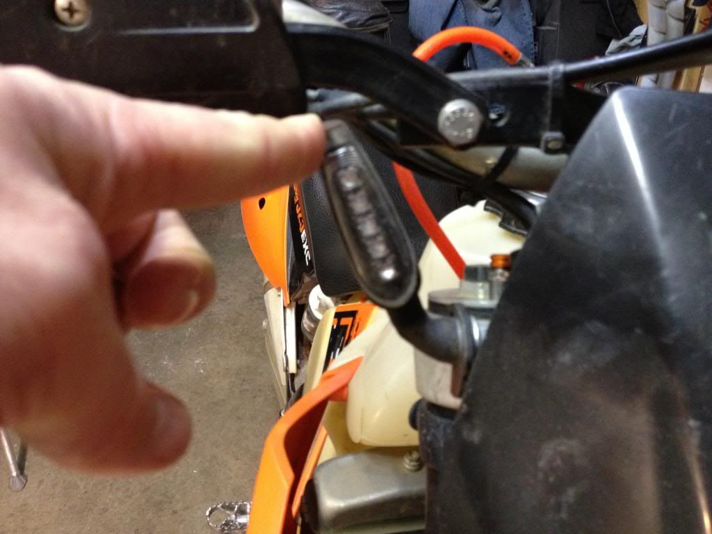
Started the reassembly of the G/S. Most of sunday was building wiring harnesses for various stuff including for the new lighting at the rear. This is what I did to modify the G/S slightly to work with the nice Koso winkies. BTW they flex very nicely") and have used them for several years on the front of the KTM and on my wike's F650
and have used them for several years on the front of the KTM and on my wike's F650
to make the stock dash indicator light work I had to alter the connection a bit and install two diodes as the ground for it cannot be achieved as it does with standard incandescent bulbs. Here is the modified wiring diagram:
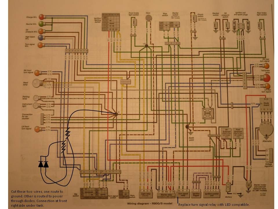
one side of the feed to the lamp was routed to ground and the other was fed through 2 diodes, one going to each of the blinker power leads, without the diodes all the blinkers would turn on instead only L or R.
I added the diodes on this side of the red connector per the schematic attached.
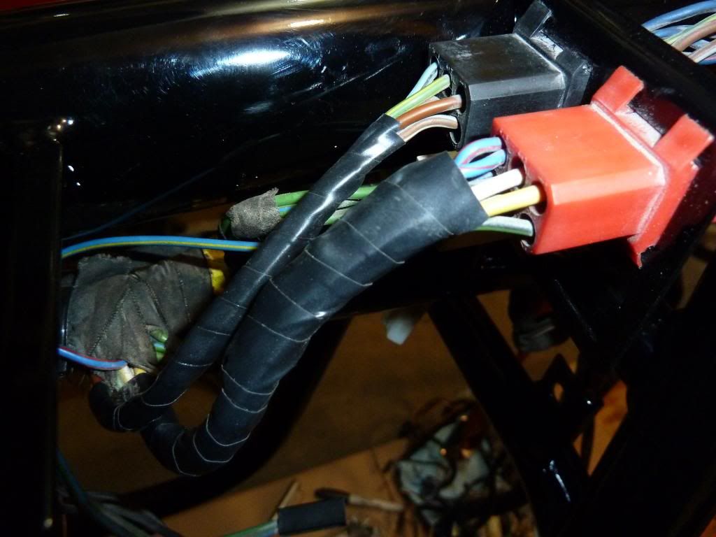
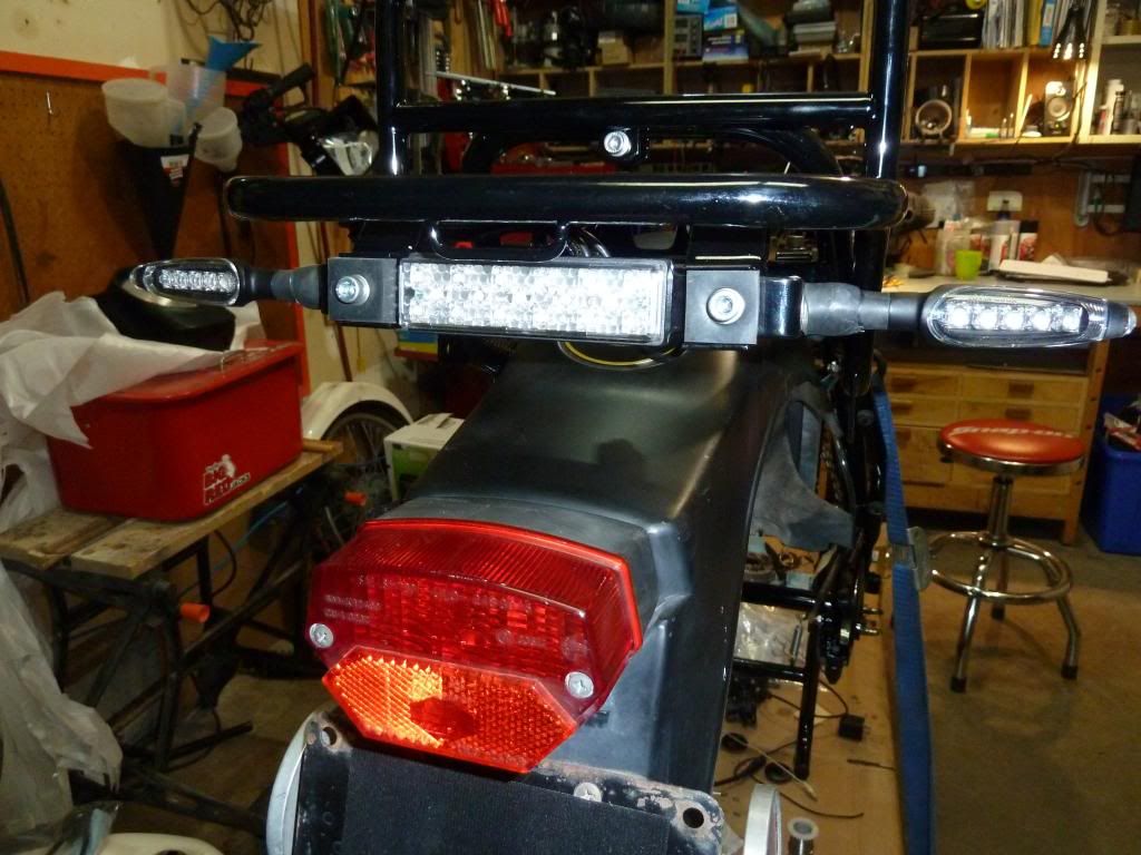
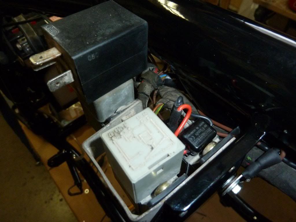
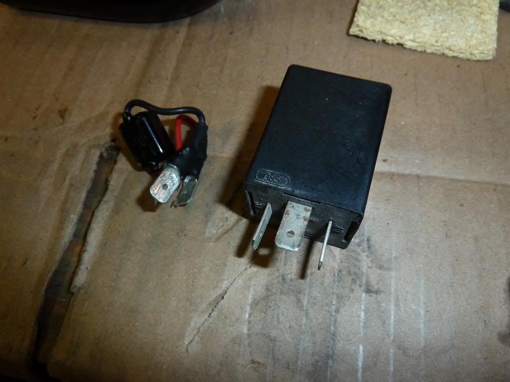
to make the LED winkies blink nicely I replaced the stock relay with a Motogadget m-Flash with flat male terminals crimped to the cable, this simply plugs into connection 49 and 49A of the flasher relay connection. It is polarity sensitive, plugged in the wrong way it does not blink. ground is not used, you could run the indicator ground wire to it, I did not think of that at the time and used a round terminal
video result so far... I have not got to the front yet.
[video]http://s421.photobucket.com/user/grahamm_album/media/led/P1020307_zps12db955d.mp4.html[/video]
Started the reassembly of the G/S. Most of sunday was building wiring harnesses for various stuff including for the new lighting at the rear. This is what I did to modify the G/S slightly to work with the nice Koso winkies. BTW they flex very nicely
and have used them for several years on the front of the KTM and on my wike's F650
to make the stock dash indicator light work I had to alter the connection a bit and install two diodes as the ground for it cannot be achieved as it does with standard incandescent bulbs. Here is the modified wiring diagram:
one side of the feed to the lamp was routed to ground and the other was fed through 2 diodes, one going to each of the blinker power leads, without the diodes all the blinkers would turn on instead only L or R.
I added the diodes on this side of the red connector per the schematic attached.
to make the LED winkies blink nicely I replaced the stock relay with a Motogadget m-Flash with flat male terminals crimped to the cable, this simply plugs into connection 49 and 49A of the flasher relay connection. It is polarity sensitive, plugged in the wrong way it does not blink. ground is not used, you could run the indicator ground wire to it, I did not think of that at the time and used a round terminal
video result so far... I have not got to the front yet.
[video]http://s421.photobucket.com/user/grahamm_album/media/led/P1020307_zps12db955d.mp4.html[/video]

