gtgt_bangbang
New member
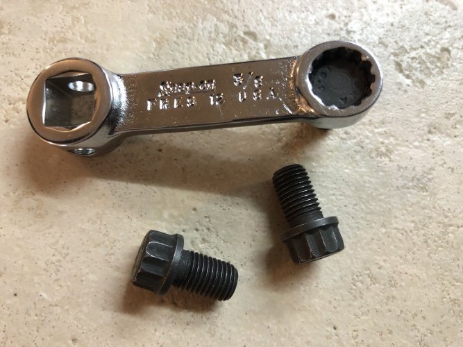
heres yet another candidate for a torque-wrench adaptor required to torque the 12pt bolts (attaching the drive shaft to the input flange of Final Drive).
Snap-On makes a 3/8" SPLINE ~ 3/8 DRIVE TORQUE ADAPTOR ( pn = FRES 12) .
Since apparently few people of Loud Sound Mind need a genuine 3/8" spline driver, there is a decent supply of v.lightly-used FRES12 on ebay around ~$20.
3/8 sockets often fit on a 10mm heads & vise versa, however this spline-type adaptor DID require a just a wee little dremel+diamond bit work to grind just the tips off the splines a fraction of a mm; after a few minutes grinding using a barrel-shaped diamond bit, the remaining splines fit nicely over the 12pt. screw heads. Still plenty of contact interface to drive the screws , the tool/splines are not significantly weakened by this mod.
Using this adaptor @ 90deg / right-angle to torque wrench handle allows the torque wrench readings to be 'close enough' that no maths are involved.
( for extra credit, I'll beat a deadhorse wrt; why the " adaptor-to-torque wrench " orientation is NOT REALLY 90deg, but that is ~close enough..., but pls dont make me dust off SOHCAOTOA-level summer school trig just to prove it !
To explain; orienting the adaptor at 90deg to torque wrench handle places the (imaginary line) moment-arm between the torque wrench's drive stub & the adaptor spline's center of rotation along the hypotenuse of the "right triangle" formed, which causes the torque applied to screw to be slightly HIGHER than the setting on the wrench (due to longer actual 'moment arm' between your hand on the wrench and the spline's socket ... Whew! BUT ) the difference will slight ... a more correct orientation would be slightly less then 90 ( roughly about 1 "ratchet click" ...
So now I can stop acquiring tools, as I finally rank a small token of Snap On buried under all that sundry brand ( can I still get a hoorah for
PennCraft ?? )
next up- a common ( especially "used 1 time!" ) Dana 44 axle "crown nut" socket is nearly perfect for the retainer nut on the final drive.
next post , me buckos, next post ...