Hi everyone.
I think I need some visual help
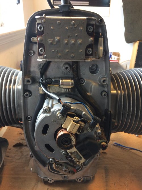
Here is a picture of my 1971 R75/5, front motor wiring with the alternator harness
As I look for images on the internet
I find many pictures on newer bikes
they have a Y harness that connects to the alternator body, and then the diode board
I went through all of my boxes from disassembly 3 years ago
I do not have that harness (used) from disassembly
also... this early stock alternator does not have the electrical connection to mount the Y harness
it has occurred to me that possibly a previous owner removed the bolt on connector and removed the old harness prior to my ownership
but what seems more likely is that this early (non fused) bike may have had different wiring for the Diode board
additionally....
I now feel like I need to confirm the wiring on my diode board now.
I have the large (Left side when facing forward with the bike) connector on the left of the diode board (large spade)
Next to the large spade I had an open terminal
but on the opposite side... (Right when facing with the bike) the spade is open on my diode board
it looks like something needs to go there... but I don't have a harness and can't figure out what
can anyone post a picture or two of their early non fused wiring in the front chest (points/alternator area)
thank you in advance
brant
I think I need some visual help
Here is a picture of my 1971 R75/5, front motor wiring with the alternator harness
As I look for images on the internet
I find many pictures on newer bikes
they have a Y harness that connects to the alternator body, and then the diode board
I went through all of my boxes from disassembly 3 years ago
I do not have that harness (used) from disassembly
also... this early stock alternator does not have the electrical connection to mount the Y harness
it has occurred to me that possibly a previous owner removed the bolt on connector and removed the old harness prior to my ownership
but what seems more likely is that this early (non fused) bike may have had different wiring for the Diode board
additionally....
I now feel like I need to confirm the wiring on my diode board now.
I have the large (Left side when facing forward with the bike) connector on the left of the diode board (large spade)
Next to the large spade I had an open terminal
but on the opposite side... (Right when facing with the bike) the spade is open on my diode board
it looks like something needs to go there... but I don't have a harness and can't figure out what
can anyone post a picture or two of their early non fused wiring in the front chest (points/alternator area)
thank you in advance
brant