• Welcome, Guest! We hope you enjoy the excellent technical knowledge, event information and discussions that the BMW MOA forum provides. Some forum content will be hidden from you if you remain logged out. If you want to view all content, please click the 'Log in' button above and enter your BMW MOA username and password.

    If you are not an MOA member, why not take the time to join the club, so you can enjoy posting on the forum, the BMW Owners News magazine, and all of the discounts and benefits the BMW MOA offers?

  • Beginning April 1st, and running through April 30th, there is a new 2024 BMW MOA Election discussion area within The Club section of the forum. Within this forum area is also a sticky post that provides the ground rules for participating in the Election forum area. Also, the candidates statements are provided. Please read before joining the conversation, because the rules are very specific to maintain civility.

    The Election forum is here: Election Forum

R75 died for no apparent reason

Looking back thru an old album, I've confirmed that both bikes ('71 and '73) had the "plunger" key on top.
The previous parts photo is from the MAX on-line fiche, which indicates that the /5 ran from 8/69 thru 7/80, so there were quite likely partial changes as the bikes evolved. We do know that (at least) the battery, alternator, swingarm, and brakes evolved in that period, so it makes sense that other parts of the electrical system evolved too.
Also, both were bought used, privately, from old guys (like I am now! gosh, over 40 years ago!) who were getting out of riding, and both seemed fairly knowledgeable about BMWs in general, so it's possible that one or both had been modified before I got it.
Both were great bikes and got me coast-to-coast a few times with zero actual issues; can't say that about the new stuff!
Really not worth worrying about... Let's get this thread back on track for dodgethatchevy.

The /5's stopped at the end of 1973. The /6's, 7's, etc. continued the who airhead line after 1973. Most changes were made between '71 and '72: fork dampening and springs, fuses in the wiring harness, carburetor's, and the extended wheelbase in 1973.
 
A non starting '72 r75 /5

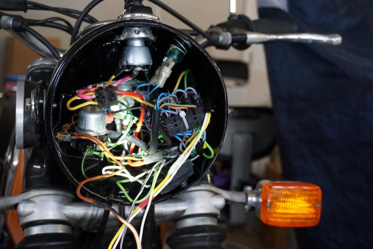
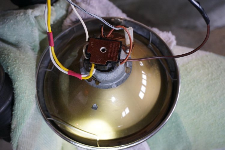
I stated this thread and have learned a lot about my newly acquired /5. I believe I got hung with the fuse deal. I finally got a couple of pictures of the inside it the headlight. I moved them to the desktop of computer. Then I hit the wall. Have been unsuccessful in transferring them to the post. Is it not possible? Some help will be greatly appreciated.
 
Headlight

DSC00332.jpgDSC00334.jpg

Pictures much too large In side. I see no sign of a fuse, but by accident I may have discovered another avenue. Raising the seat I discovered a small black object with 3 wires coming from it. To my amazement, one wire went directly to the pos battery and a second wire went directly to the neg battery post. The third wire, really a cable ran down the length of the rear fender and ended with a black type of connector. The connector was closed with a spring flap. Looking inside showed a a metal connector of a type I have never seen before.

I am planning opening the device from witch the 3 wires came from and look for a fuse. I disconnect the battery leads before I start.

rickt
 
Why would a device with a wire running to the back of the bike have anything to do with the engine starting or not?
 
Fuses

Look at the picture that you posted. At the 5 o'clock position you will see a black rubber block that is holding two fuse containers. The one with the green wire on one end and the green/black on the other holds an 8amp fuse that powers the horn, ignition and brake light.
You didn't mention that you had an ignition switch conversion. That changes a few things but the color coding of the wires appears to be unmolested.
 
Oh, and that black connector block with all the wires going into and out of that is just hanging at the 3 o'clock position is usually positioned at the 7 o'clock position and held onto the headlight shell by a phillips head sheet metal screw screwed in from the outside. You'll see a hole for it.
 
Look at the picture that you posted. At the 5 o'clock position you will see a black rubber block that is holding two fuse containers. The one with the green wire on one end and the green/black on the other holds an 8amp fuse that powers the horn, ignition and brake light.
You didn't mention that you had an ignition switch conversion. That changes a few things but the color coding of the wires appears to be unmolested.

I just purchased the bike. I know nothing of its history, What exactly denotes a ignition switch conversion?
 
original switch

This is one of those "you have to see it to understand" kinda things. I was hoping that someone more adept at computers would post a picture but I don't see that happening so I'll start at the outside and work inward with a description because I don't have any photos.
On the top of the headlight shell you should see a chrome, sort of teardrop shaped fitting in front of the instrument cluster. There should be a black plastic sliding cap at the rear that slides to the rear. If your replacement switch was installed well then the key that you have should fit in with the plastic cover pulled back.
The original "key" was simply a notched pin that went down into the switch and made basic contact with a springy flat tab that made a connection similar to a set of ignition points. The pin had a plastic handle that could be rotated left or right to turn on either the parking lights or the parking lights and headlight. An auxiliary key was all metal and served the same purpose.
Inside the shell you would see an insulated flat board that was held in place by four tabs that went through the board and were bent over to hold it in place.
On the board were drum like connectors with holes in the side for insertion of wires and a screw on the end to hold the wires in place.
I think that that is all you need to know or at least that is the best explanation that I can give.
Check your personal message box.
 
Dumb as a brick

Look at the picture that you posted. At the 5 o'clock position you will see a black rubber block that is holding two fuse containers. The one with the green wire on one end and the green/black on the other holds an 8amp fuse that powers the horn, ignition and brake light.
You didn't mention that you had an ignition switch conversion. That changes a few things but the color coding of the wires appears to be unmolested.

Yes indeed, there it was staring right at me. Thanks for the most appropriate response. Now for my second dumb question: How does one separate the two plastic pieces to free the fuse that hides inside?
 
Follow up

Success is nearly at hand. Following the recommendations, the black plastic holder was opened and therein was the defective fuse. A quick call to Bob's will result in a replacement arriving at the week. All that remains is installing the new fuse and hoping for the best. Don't yet know why the fuse blew.

rickt
 
fuses

Just a reminder, the fuse is an 8amp fuse commonly found in a lot of independent VW repair shops as well as most major auto parts stores. You can sometimes save a lot of time and money by going there first.
 
Success is nearly at hand. Following the recommendations, the black plastic holder was opened and therein was the defective fuse. A quick call to Bob's will result in a replacement arriving at the week. All that remains is installing the new fuse and hoping for the best. Don't yet know why the fuse blew.

rickt

Success is nearly at hand? So sorry rickt, but now you can begin to address the problem. Not to worry, you are making progress! I suggest you do not increase the amperage of that fuse if it blows again. Best to diagnose the problem before you burn up wires. Good luck!
 
Success sort of

It has been much too long since I've been able to get back to the R75. The single 8 amp fuse was the culprit. The bike started easily. I will hope that the problem was caused by my rather inept attempt to connect a battery tender back near the start of this story. In any case I find myself challenged by the installation of the light assembly back into the case. I saw on the parts fiche a gasket between the assembly of wires and bulb and the front bulb case and so I ordered it. No gasket was on the bike in the beginning. Now I find myself challenged with the task of installing the gasket and "jamming" the bunch of wires back into the headlight bezel. Another problem I will face is securing the wires and bulb to the bezel. It you return to one of my early posts, you will note that the chrome ring was secured to the bezel with a tiny spring that few away when I finally pulled it from the chrome ring. In the process, the tiny black cube to which the spring was attached was also lost. At this point, I would appreciate any and all suggestions for installing and securing the light fixture into the headlight bezel.

l must apologize, my ability to locate the proper words is due to a stroke 10 years ago.
 
Back
Top