• Welcome, Guest! We hope you enjoy the excellent technical knowledge, event information and discussions that the BMW MOA forum provides. Some forum content will be hidden from you if you remain logged out. If you want to view all content, please click the 'Log in' button above and enter your BMW MOA username and password.

    If you are not an MOA member, why not take the time to join the club, so you can enjoy posting on the forum, the BMW Owners News magazine, and all of the discounts and benefits the BMW MOA offers?

  • Beginning April 1st, and running through April 30th, there is a new 2024 BMW MOA Election discussion area within The Club section of the forum. Within this forum area is also a sticky post that provides the ground rules for participating in the Election forum area. Also, the candidates statements are provided. Please read before joining the conversation, because the rules are very specific to maintain civility.

    The Election forum is here: Election Forum

InView Wireless Brake and Turn Signal installation

scootrp125x

They call me Gort
I have been wanting a GS for decades and finally added one to the 2004 R1150RT in my garage. I went over to the dark side and bought a 2013R1200 GSW.

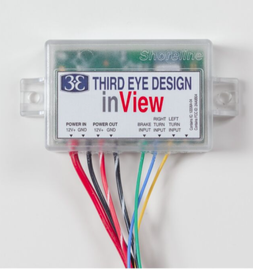
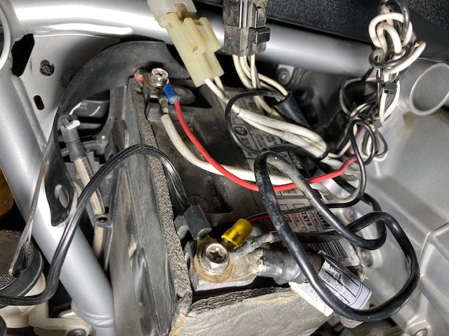
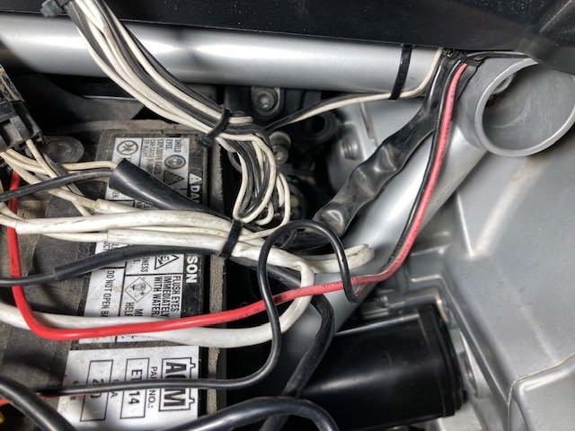
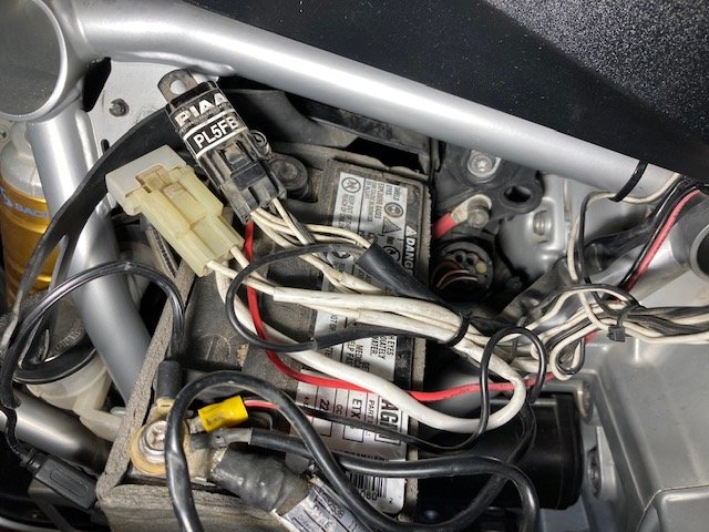
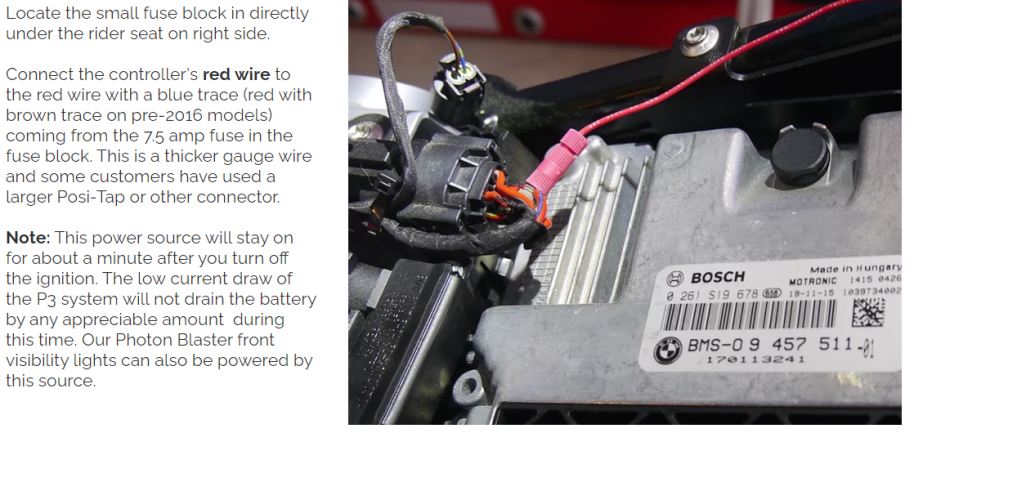
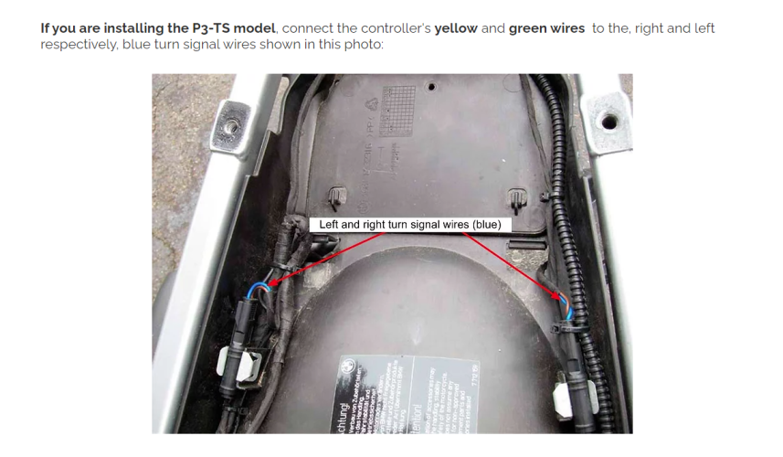
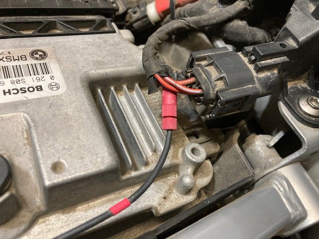
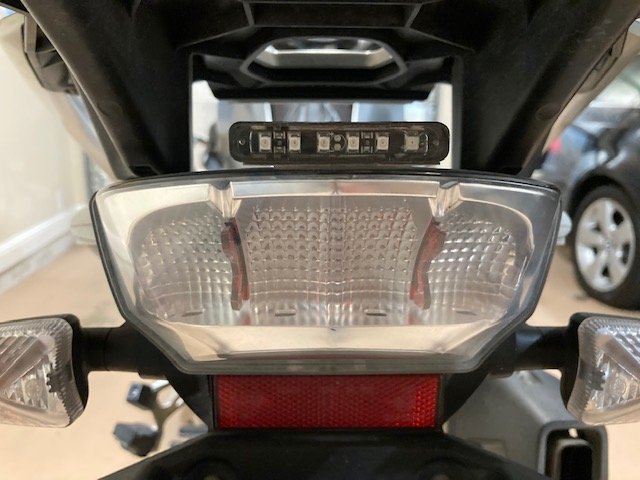
I installed the InView tranceiver on my RT with help from the Forum. Now I want to add a tranceiver to my GS but I'm unsure about the wiring. There are some wires visible under the rear seat, blue wires on each side and a module of some kind with a red, a brown and two white wires. I need to tap into the right and left turn signal wires and to the brake wire. I also need a switched power source such as the tail light wire. Can anyone tell me which wires I should look for?

Thanks for the advice! Mark

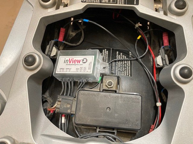
I'll try to post a picture of the transceiverInView.png
 

Attachments

  • InView.png
    InView.png
    394 KB · Views: 125
The two blue wires - each with a different color stripe - are the turn signal wires. You should be able to tell which by their position. I can't help with the brake.
 
The tail lights are:

Blue/Black: Right turn signal
Blue/Red:Left turn signal
Grey/Red: Tail light
Grey Black with Yellow dot: Brake
Brown: Ground

Under the riders seat you'll see two fuses, I taped into one of them both would be good to use as a switched power source for your relay. I'd wire the positive to a fuse box or direct to the battery.
 
Thanks for the additional information. I will research these wires and be ready when the transceiver arrives in a few days.

Mark
 
Out of curiosity, what is a InView tranceiver and what does it do?


It is a helmet mounted LED light that transmits the turn signal and brake light signals to the back of my helmet. It lights up very brightly and makes me more visible to drivers behind me.

Here is a Youtube link to a review done by MOA member Moshe K Levy: https://www.youtube.com/watch?v=TpGMOg6aINw

I'm a happy customer and have nothing to do with this company.
 
Want to add EzCan to my bike, what are these wires going to my battery??

I'm finally getting around to working on my bike to add the InView helmet light transceiver to my bike. First I think I would like to put a Hex EzCan on the bike to make the Inview installation easy and to clean up some wiring from aftermarket Rigid Industries LED lights and PIAA horns that a previous owner had installed. It looks like some of the wiring from these lights and horns are connected to the battery.

I hope these pictures are good enough for someone to help me figure out what they are attached to before they connect to the battery. There is a set of red and black wires coming from under the gas tank. These wires are connected directly to the battery.

There is also a set of black and white wires coming from under the gas tank that are first connected to the wiring harness that says PIAA, and then go to a fuse to the left of the PIAA box. There is also a set of two black and two white wires connected to the PIAA harness.

There is also a white wire that appears to be hooked up to something behind the head light with a Posi tap connector. I'm guessing this is for the horn or lights so that they can be used with the BMW handlebar button.

So to summarize, there is one set of black and red wires, each wire is connected to the battery. There is also a set of black and white wire coming from the PIAA harness that is connected to the battery. I would guess that the PIAA harness is for the PIAA horns and that the black and red wires are for the LED lights. Can I take each set and hook them up to each connector on the EzCan? I could take the tank off to trace these wires but I'd rather not if I don't have to.

I will attach some pictures that I hope will help explain the situation. Thanks in advance. Mark
 

Attachments

  • Battwires1.jpg
    Battwires1.jpg
    115.9 KB · Views: 73
  • Battwires2.jpg
    Battwires2.jpg
    103.5 KB · Views: 71
  • Battwires3.jpg
    Battwires3.jpg
    84.2 KB · Views: 72
  • Battwires4.jpg
    Battwires4.jpg
    92.7 KB · Views: 71
  • Battwires6.jpg
    Battwires6.jpg
    119.9 KB · Views: 71
In the last pic, the PL5FB looks like a relay to allow the horn to be disconnected when the bike is not "on" and/or to allow direct draw from the battery when the horn button is engaged.

It could also be the same type of thing for the aux light - gets a signal from the tapped light wire which triggers the relay and then powers the light directly from the battery.

The PL5FB is a PIAA relay so I would assume it is for the aux lights.
 
In the last pic, the PL5FB looks like a relay to allow the horn to be disconnected when the bike is not "on" and/or to allow direct draw from the battery when the horn button is engaged.

It could also be the same type of thing for the aux light - gets a signal from the tapped light wire which triggers the relay and then powers the light directly from the battery.

Thanks. Can I connect those wires to the EzCan, since EzCan will take the place of the battery as the source of power?
 
You will need to figure out the signal vs power wires, and whether it's for horn, and how to maintain the control... other than that I see no reason not to. (I have no experience with the EZ-CAN...) I just re-read and see that the horn is PIAA.

And PG - the horn is a PIAA, the lights he said were Rigid Industries, so the relay is definitely for the horn.

Thanks
 
Finally installed the Inview tranceiver

I decided to hold off on installing the HexEzCan for now and finish installing the Inview tranceiver. I thought I would put my final installation information here for anyone else that needs it someday. The Skeene lighting instructions and pictures were pretty much the way to go. Thanks to everyone who also gave me this information.

Blue/Black: Right turn signal
Blue/Red:Left turn signal
Grey Black with Yellow dot: Brake light
Brown: Ground
Red/Brown fused wire under riders seat: Power

I removed the rear grab rail behind the passengers seat and rear carrier under the passengers seat. Then I removed the license plate holder assembly by removing two screws. Then I removed three clips holding the rear tail light to access the rear brake light wires.

I connected the Inview wires to the Grey/Black with Yellow Dot Brake light wire, Left Blue/Red and Right Blue/Black turn signal wires, I fastened the Brown Ground wire to the frame in a cross bar with holes in it between the rider and passenger seat. The Inview power wire went to the Red/Brown fused wire under the passenger seat. Here are the Skeene pictures:
 

Attachments

  • Fusewire1.png
    Fusewire1.png
    656.6 KB · Views: 19
  • Turnsignalwires1.png
    Turnsignalwires1.png
    664.4 KB · Views: 19
  • Finalwires1.png
    Finalwires1.png
    832.8 KB · Views: 19
  • Taillightwires1.png
    Taillightwires1.png
    808 KB · Views: 19
  • Skeenpic1.png
    Skeenpic1.png
    839.2 KB · Views: 2
Last edited:
Final installation

Here are three of my own pictures of the Invew Tranceiver located under the passenger seat, power wire connection to the fused wire under the riders seat and the small LED light that is on top of the rear tail light. The Inview tranceiver has a decelerometer and this LED light provides a brake light when decelerating without using the bike brake levers.
 

Attachments

  • Invview1.jpg
    Invview1.jpg
    104.5 KB · Views: 19
  • Inview2.jpg
    Inview2.jpg
    110.3 KB · Views: 19
  • Inview3.jpg
    Inview3.jpg
    81.3 KB · Views: 19
Back
Top