gtrider
52184
I recently installed a set of Moto Verholen brackets for lowering the footpegs on my 2010 K1300GT, sourced from Pirates Lair. Included in the kit was an aluminum piece designed to clamp around the brake pedal of a K1200S and lower the brake pedal by adding thickness to the pedal. However, no such fix was included for the K1300GT, which uses a different pedal than the K1200S. I was not comfortable with the relationship between the now-lowered footpegs and the existing brake pedal location, so started researching possible fixes by asking for photos in a thread located here. Rather than further mess up that thread, and in order to keep this post easily reachable in a search, I'm starting this new thread. Note that what I'm illustrating here is a modification to a critical safety system that should only be undertaken by a skilled machinist and mechanic and that a modification such as this is done at your own risk.
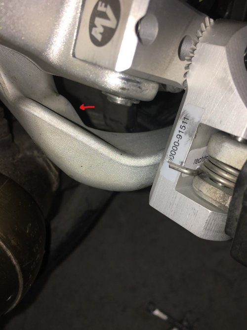
The pedal stop for the K1300GT is on the back side of the pedal, as shown in the photo below. The stop is just a flat portion on the pedal and designed to bottom against the frame where it meets the footpeg mounting arm bolted to the frame. The red arrow in the photo below shows the section of the brake pedal that acts as the stop.
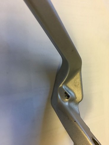
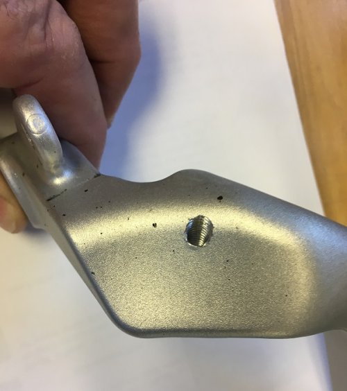
Removing the pedal and flipping it over showed the stop to be a flat spot on the pedal, and the pedal to have ample thickness to install an adjustable stop setup without worry of pedal breakage. I determined the correct location for an adjustable stop was near the outer edge of the flat stop area, then jigged up the pedal so I could drill a 13/64" hole perpendicular to the flat stop area, all the way through the pedal. I then tapped the hole for a 6mm x 1.0 thread as shown in the photos below:
Hole Location:
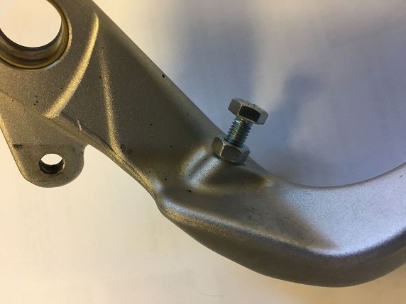
And installed a 6mm x 1.0 bolt and locknut:
The pedal stop for the K1300GT is on the back side of the pedal, as shown in the photo below. The stop is just a flat portion on the pedal and designed to bottom against the frame where it meets the footpeg mounting arm bolted to the frame. The red arrow in the photo below shows the section of the brake pedal that acts as the stop.

Removing the pedal and flipping it over showed the stop to be a flat spot on the pedal, and the pedal to have ample thickness to install an adjustable stop setup without worry of pedal breakage. I determined the correct location for an adjustable stop was near the outer edge of the flat stop area, then jigged up the pedal so I could drill a 13/64" hole perpendicular to the flat stop area, all the way through the pedal. I then tapped the hole for a 6mm x 1.0 thread as shown in the photos below:
Hole Location:


And installed a 6mm x 1.0 bolt and locknut:


