• Welcome, Guest! We hope you enjoy the excellent technical knowledge, event information and discussions that the BMW MOA forum provides. Some forum content will be hidden from you if you remain logged out. If you want to view all content, please click the 'Log in' button above and enter your BMW MOA username and password.

    If you are not an MOA member, why not take the time to join the club, so you can enjoy posting on the forum, the BMW Owners News magazine, and all of the discounts and benefits the BMW MOA offers?

  • Beginning April 1st, and running through April 30th, there is a new 2024 BMW MOA Election discussion area within The Club section of the forum. Within this forum area is also a sticky post that provides the ground rules for participating in the Election forum area. Also, the candidates statements are provided. Please read before joining the conversation, because the rules are very specific to maintain civility.

    The Election forum is here: Election Forum

1992 K75 Stamdard - Electrical question

105643

New member
I just bought a 1992 K75 from my friend's widow (long sad story, may he rest in peace) and was going through it to fix what is needed and to remove accessories that are no longer required (Autocom system, for one). I found a couple of auxiliary circuits that weren't attached to anything (no tape on the ends of the wires that were switch hot) and removed those.

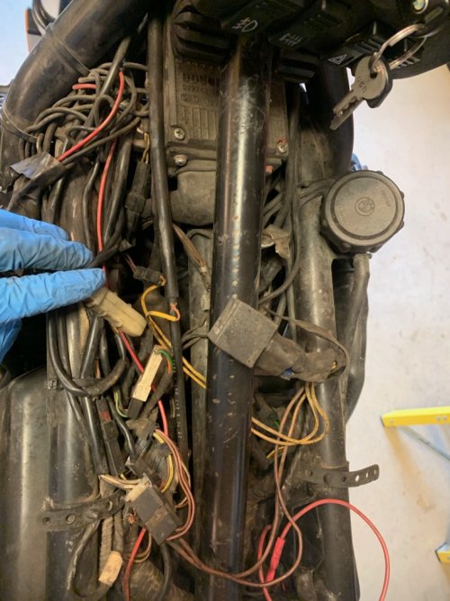
I did find two brown loose wires that were apparently just pushed into a connector at one point (possibly the one in the following picture, middle left?)
Wiring1.jpg
:huh

Those loose brown wires attach to a non-factory relay. Also connected to said relay are two yellow wires that are also just pushed into the factory connector that has a CHOKE label on it (or it did until I touched and moved it and then it fell off)
Wiring2.jpg

I have not looked further at the relay to figure out which wire is supposed to do what (power in/output/common). Do y'all know of any common 'mods' that would utilize said connectors? I have read that BMW (at some point) decided that owners really didn't need an indicator for when the choke was on, but they never removed said connection from the factory loom. I thought that CHOKE connector went to the instrument panel (I could be wrong), but why would one need a relay to power an indicator light? :dunno

Thanks in advance.

Indy Bill
 

Attachments

  • Wiring3.jpg
    Wiring3.jpg
    239.6 KB · Views: 64
more info

I traced the black/white connector (the middle left of the second picture) and that goes to the left hand accessory light switch. What I referred to as the disconnected brown wires actually connect to the coil of the relay (relay terminals 85 and 86). The two yellow wires are connected to the high current (normally open and common, relay terminals 30 and 87) on the relay (going to the CHOKE connector).

Note: the left hand accessory light switch controls the right hand driving light. Switch on = light on).

Assuming that my previous guesses were correct as to
1 - where the brown wires fell out of, and
2 - that this relay was put in to provide power for the choke on indicator
I pushed the wires back into the connectors, crossed my fingers and turned on the ignition key. Once I was satisfied that the magic smoke would not be released I checked and the RH driving light was on with the accessory switch off. :scratch

I finally just removed that relay and the wires. Problem solved!

Indy Bill
 
Bill,

It sounds like they were using the choke light in the instument cluster as an indicator light for the auxiliary lights. Auxiliary lights on=yellow choke indicator light on dash on.

The relay would be used to "jump" the two wires to the connector. The bulb is fed + from the cluster circuit board. The purple wire is on the - side of the bulb. You will read 12v+ on the purple wire because that is the voltage going through the bulb, but you can't use this for switched power because the bulb will act like a fuse and blow with the smallest load. But it might be possible that the bulb would handle the current of the coil side of the relay. The power goes from the purple wire, through the switch (on the earlier bikes) and is made by the switch based on the choke (fast idle) switch.:dunno Then it is grounded through the return brown wire. BMW uses brown for almost all ground wires and does most of its switching on the ground side when possible.

You can test the choke light by putting a paper clip in the two pin holes of that choke connector with the key (and maybe the kill switch) in the run position.

The only thing BMW left out of that choke light circuit was the switch on the throttle body and the graphic in the tach face. The wiring and the bulb are there. Add the switch, the light works as the earlier bikes did.


:dance:dance:dance
 
Thanks. I survived 15 years without a choke light on my RT. I can figure something else out on these lights.

I would rather have a good triangle pattern in the front for daytime running/noticeability. Maybe some small Denali lights on all the time with the headlight, and larger Denalis for driving lights?

More questions possibly coming later

Indy Bill
K75 Neophyte
 
Back
Top