• Welcome, Guest! We hope you enjoy the excellent technical knowledge, event information and discussions that the BMW MOA forum provides. Some forum content will be hidden from you if you remain logged out. If you want to view all content, please click the 'Log in' button above and enter your BMW MOA username and password.

    If you are not an MOA member, why not take the time to join the club, so you can enjoy posting on the forum, the BMW Owners News magazine, and all of the discounts and benefits the BMW MOA offers?

  • Beginning April 1st, and running through April 30th, there is a new 2024 BMW MOA Election discussion area within The Club section of the forum. Within this forum area is also a sticky post that provides the ground rules for participating in the Election forum area. Also, the candidates statements are provided. Please read before joining the conversation, because the rules are very specific to maintain civility.

    The Election forum is here: Election Forum

1977 BMW R100RS Restore Project

1977 R100RS Project: Remove Drive Shaft & Swing Arm Bearings

I'm going to have the swing arm powder coated. So I remove the drive shaft to avoid any possibility of damage to it and the swing arm bearings. I will replace the swing arm bearings as they are likely 40 years old and there is rust in many places on the bike so it's possible the swing arm bearings have not been cared for.

<a title="Swing Arm with Drive Shaft" href="https://www.flickr.com/photos/brook-reams/30147200503/in/album-72157674702984351/"><img src="https://c8.staticflickr.com/6/5710/30147200503_93ef955e52_z.jpg" alt="Swing Arm with Drive Shaft Inside" width="640" height="480" /></a>
Swing Arm with Drive Shaft Inside

I use a tool from <a href="http://www.cycleworks.net" target="_blank">Cycle Works</a> to pull the bell housing off the end of the drive shaft that fits into the rear drive unit. Then the shaft slides out of the swing arm housing toward the transmission end of the swing arm. The tool made it very easy to remove the bell housing. The housing is secured by a nut that is torqued quite high and by a taper in the housing and the end of the drive shaft, so it can take a lot of leverage to break the bell housing loose from the drive shaft. Mine came off quite easily.

You can read about how I do this work here:
<ul class="children">
<li class="page_item page-item-4694"><a href="http://brook.reams.me/bmw-motorcyle-rebuilds/1977-bmw-r100rs-rebuild-project-index/33-bmw-1977-r100rs-remove-drive-shaft-swing-arm-bearings/">33 BMW 1977 R100RS Remove Drive Shaft & Swing Arm Bearings</a></li>
</ul>
Here are a couple pictures from the write-up.

<a title="Drive Shaft Bell Housing Nut" href="https://www.flickr.com/photos/brook-reams/30481914790/in/album-72157674702984351/"><img src="https://c7.staticflickr.com/6/5468/30481914790_185fe6d372_z.jpg" alt="Drive Shaft Bell Housing Nut" width="640" height="480" /></a>
Drive Shaft Bell Housing Nut

<a title="Cycle Works Drive Shaft Bell Housing Removal Tool" href="https://www.flickr.com/photos/brook-reams/30746333886/in/album-72157674702984351/"><img src="https://c7.staticflickr.com/6/5532/30746333886_e0c4cb00d9_z.jpg" alt="Cycle Works Drive Shaft Bell Housing Removal Tool" width="640" height="480" /></a>
Cycle Works Drive Shaft Bell Housing Removal Tool

<a title="Cycle Works Drive Shaft Bell Housing Removal Tool" href="https://www.flickr.com/photos/brook-reams/30147197043/in/album-72157674702984351/"><img src="https://c4.staticflickr.com/6/5609/30147197043_1ea1dcbabc_z.jpg" alt="Final Assembly of Cycle Works Drive Shaft Bell Housing Removal Tool" width="640" height="480" /></a>
Final Assembly of Cycle Works Drive Shaft Bell Housing Removal Tool

<a title="Drive Shaft Removed From Swing Arm" href="https://www.flickr.com/photos/brook-reams/30147196513/in/album-72157674702984351/"><img src="https://c2.staticflickr.com/6/5557/30147196513_48a133cc31_z.jpg" alt="Drive Shaft Removed From Swing Arm" width="640" height="480" /></a>
Drive Shaft Removed From Swing Arm
 
1977 R100RS Project: Remove, Refurbish, Install Clutch

Folks,

I documented this work here:

The clutch spring had oil on it and someone botched the spline lube putting moly paste on the outside of the clutch plate spline. So,all is better now. :)

I included a short video of how I installed refurbished clutch (by Southland Clutch, great folks to deal with) at the end of the document.

TL/DR: Here is a link to the video:

--> 1977 BMW R100RS Clutch Install

I also setup a YouTube channel to support my write-ups as I seem to be making a number of small videos as I proceed with this project. I'm learning as I go about how to use short video clips effectively. It's an interesting tool.

--> https://www.youtube.com/channel/UCQzNs09m3GMIJmFTBFEeM6w

I hope this is helpful.

Best.
Brook Reams.
 
Brook -

Sure is nice working on a clutch on the bench, huh?? In the bike, it's a bit harder!! BTDT. Regarding the Cycleworks bolts you used to initially hold the clutch pack onto the flywheel. You can do the same thing with even longer metric bolts from the big box hardware store. My point is that once three bolts are run into the flywheel a good number of threads, I used an open end wrench on the nut to move the clutch pack closer to the flywheel, compressing the clutch spring. I used a large flat washer between the nut and the clutch pack to keep the nut from scratching the pressure plate. Attached is a picture from when I was doing my clutch a number of years ago.

I'm thinking that's the way your bolts from Cycleworks were intended to be used. But in your case, as long as the bolts were short enough, you can simply run them in as you were doing. However, if they bottom out on the threads, then you would have to use the nut.

Keep up the good work. :thumb I've included your video channel in the list of online videos I've been able to find.
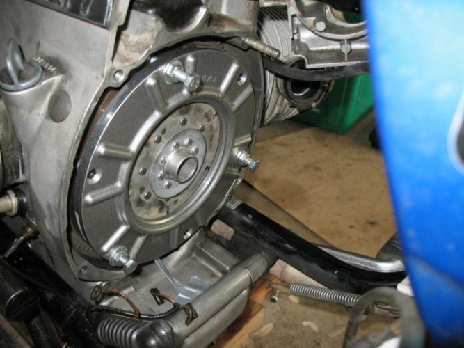
ClutchBoltStart.jpg
 
SNIP ....

I'm thinking that's the way your bolts from Cycleworks were intended to be used. But in your case, as long as the bolts were short enough, you can simply run them in as you were doing. However, if they bottom out on the threads, then you would have to use the nut.

Keep up the good work. :thumb I've included your video channel in the list of online videos I've been able to find.

< ============================ >

Hi Kurt,

Yes, I kept the washers and nuts on the clutch removal bolts when I installed the clutch pack so the washer kept the bolt face from scratching the compression plate.

Thank you for adding my video channel to your collection. I hope to add short, non-profane clips when a video can clarify a procedure. Since you lumped mine in with others from someone else who loves a certain anglo-saxon expletive, maybe you ought to clarify the sources of the videos in the introduction since not all of them are from him?

Right now they are more a compliment to my written procedures than stand-alone items.

I have powder coated parts back, brake calipers are out for new blue anodizing and paint work should be back "soon". I hope to be adding more content as the pace of putting things back to together starts to pick up.

Best.
Brook.
 
Last edited:
1977 R100RS Project: Rear Main Oil Seal, Oil Pump Inspection, Oil Pump Cover O-ring

Folks,

I completed work on the front of the engine when I replaced the timing chain, crankshaft timing gear, front main seal and crankshaft nose bearing. I also replaced the three seals in the timing chest cover. *You can see how I did that work here:
<ul class="children">
<li class="page_item page-item-4596"><a href="http://brook.reams.me/bmw-motorcyle-rebuilds/1977-bmw-r100rs-rebuild-project-index/11-bmw-1977-r100rs-replace-timing-chain-crankshaft-timing-gear-nose-bearing/">11 BMW 1977 R100RS Replace Timing Chain, Crankshaft Timing Gear & Nose Bearing</a></li>
</ul>
So the next area of work is the rear of the engine. I removed the clutch and had it refurbished by <a href="http://www.southlandclutch.com" target="_blank">Southland Clutch</a>. I removed the flywheel, replaced the rear crankshaft main seal and the oil pump cover o-ring. While I had the pump cover off, I measured the clearances of the oil pump gears and found them all good and toward the low end of the allowable wear limit. Here is how I did this work:
<ul class="children">
<li class="page_item page-item-4715"><a href="http://brook.reams.me/bmw-motorcyle-rebuilds/1977-bmw-r100rs-rebuild-project-index/11-bmw-1977-r100rs-replace-rear-main-seal-oil-pump-cover-o-ring/">21 BMW 1977 R100RS Remove, Refurbish, Install Clutch</a> <-- This gets removed before removing the flywheel</li>
<li class="page_item page-item-4715"><a href="http://brook.reams.me/bmw-motorcyle-rebuilds/1977-bmw-r100rs-rebuild-project-index/11-bmw-1977-r100rs-replace-rear-main-seal-oil-pump-cover-o-ring/">11 BMW 1977 R100RS Replace Rear Main Seal & Oil Pump Cover O-Ring</a></li>
</ul>
I added a new full advance timing mark to the flywheel at 25° BTDC. I have dual plug heads and the advice from Tom Cutter at Rubber Chicken Racing Garage is to retard the full advance by 6° by retarding the "S" timing by 3° and limiting the full advance by another 3°. Before doing this, I did some digging to learn more about the flywheel in this bike and the automatic timing unit (ATU) and documented BMW flywheel changes in the /5, /6 and /7-R100 series of motors and the ATU's. You can find that information here:
<ul class="children">
<li class="page_item page-item-4717"><a href="http://brook.reams.me/bmw-motorcyle-rebuilds/1977-bmw-r100rs-rebuild-project-index/12-bmw-1977-r100rs-changes-to-ignition-for-dual-plug-heads/">12 BMW 1977 R100RS Changes To Ignition For Dual Plug Heads</a></li>
<li class="page_item page-item-4621"><a href="http://brook.reams.me/bmw-motorcyle-rebuilds/1977-bmw-r100rs-rebuild-project-index/12-bmw-1977-r100rs-install-dyna-iii-electronic-ignition-refurbish-automatic-timing-unit-atu/">12 BMW 1977 R100RS Install Dyna III Electronic Ignition-Refurbish Automatic Timing Unit (ATU)</a></li>
</ul>
Next up is to remove the pistons, rings and connecting rods, see how the rod big end bearings look, remove the rings, clean the pistons and inspect them and then make decisions about what needs to be done to these components.

Here are a couple pictures from the write-ups above.

<a title="M6 x 10 mm Bolt In Alternator Rotor Allen Head Bolt" href="https://www.flickr.com/photos/brook-reams/30800494590/in/album-72157675205320686/"><img src="https://c7.staticflickr.com/6/5526/30800494590_e3ce72464e_z.jpg" alt="M6 x 10 mm Bolt In Alternator Rotor Allen Head Bolt" width="640" height="480" /></a>
M6 x 10 mm Bolt In Alternator Rotor Allen Head Bolt

<a title="Front Cover Snug with Gap At Bottom Ensures Flywheel is Blocked Toward Rear" href="https://www.flickr.com/photos/brook-reams/30800494290/in/album-72157675205320686/"><img src="https://c3.staticflickr.com/6/5685/30800494290_3a2815117c_z.jpg" alt="Front Cover Snug with Gap At Bottom Ensures Flywheel is Blocked Toward Rear" width="640" height="480" /></a>
Front Cover Snug with Gap At Bottom Ensures Flywheel is Blocked Toward Rear

<a title="Added Flywheel Index Marks" href="https://www.flickr.com/photos/brook-reams/30360563573/in/album-72157675205320686/"><img src="https://c6.staticflickr.com/6/5577/30360563573_841873a985_z.jpg" alt="Added Flywheel Index Marks" width="640" height="480" /></a>
Added Flywheel Index Marks

<a title="Oil Leak From Crankshaft Bolt Hole (1:00)" href="https://www.flickr.com/photos/brook-reams/30360563883/in/album-72157675205320686/"><img src="https://c4.staticflickr.com/6/5548/30360563883_f512c2306c_z.jpg" alt="Oil Leak From Crankshaft Bolt Hole (1:00)" width="640" height="480" /></a>
Oil Leak From Crankshaft Bolt Hole (1:00)

<a title="Groove Cut Into Flywheel By Rear Main Crankshaft Seal" href="https://www.flickr.com/photos/brook-reams/30800492870/in/album-72157675205320686/"><img src="https://c7.staticflickr.com/6/5587/30800492870_abbbaf53a7_z.jpg" alt="Groove Cut Into Flywheel By Rear Main Crankshaft Seal" width="640" height="480" /></a>
Groove Cut Into Flywheel By Rear Main Crankshaft Seal

<a title="Clutch Ready to Remove" href="https://www.flickr.com/photos/brook-reams/31258685532/in/album-72157677288919056/"><img src="https://c5.staticflickr.com/6/5732/31258685532_8e71332183_z.jpg" alt="Clutch Ready to Remove" width="640" height="480" /></a>
Ready To Remove Clutch

<a title="Accumulated Crud on Transmission Shelf" href="https://www.flickr.com/photos/brook-reams/31258683902/in/album-72157677288919056/"><img src="https://c7.staticflickr.com/6/5559/31258683902_374a590ae0_z.jpg" alt="Accumulated Crud on Transmission Shelf" width="640" height="480" /></a>
Accumulated Crud on Transmission Shelf

<a title="Nut Distance From Bolt Head" href="https://www.flickr.com/photos/brook-reams/31258684922/in/album-72157677288919056/"><img src="https://c3.staticflickr.com/6/5502/31258684922_a628e70143_z.jpg" alt="Clutch Removal Bolts-Nut Distance From Bolt Head" width="640" height="480" /></a>
Clutch Removal Bolts-Nut Distance From Bolt Head

<a title="Clutch Alignment Marks" href="https://www.flickr.com/photos/brook-reams/31258684532/in/album-72157677288919056/"><img src="https://c5.staticflickr.com/6/5700/31258684532_828e9b26ee_z.jpg" alt="Clutch Alignment Marks" width="640" height="480" /></a>
Clutch Alignment Marks

<a title="Diaphragm Spring with Streaks of Lubricant :-(" href="https://www.flickr.com/photos/brook-reams/31258683662/in/album-72157677288919056/"><img src="https://c7.staticflickr.com/6/5735/31258683662_1517e83cb3_z.jpg" alt="Diaphragm Spring with Streaks of Lubricant :-(" width="640" height="480" /></a>
Diaphragm Spring with Streaks of Lubricant :-(

<a title="New Diaphragm Spring Height & Partial Part Number (Right)" href="https://www.flickr.com/photos/brook-reams/30617218403/in/album-72157677288919056/"><img src="https://c4.staticflickr.com/6/5457/30617218403_1d9e61c682_z.jpg" alt="New Diaphragm Spring Height & Partial Part Number (Right)" width="640" height="480" /></a>
New Diaphragm Spring Height & Partial Part Number (Right)

<a title="Starting To Clean Flywheel Housing" href="https://www.flickr.com/photos/brook-reams/30800492040/in/album-72157675205320686/"><img src="https://c1.staticflickr.com/6/5634/30800492040_961a7c2652_z.jpg" alt="Starting To Clean Bell Housing" width="640" height="480" /></a>
Starting To Clean Bell Housing

<a title="Clutch Housing After Cleaning" href="https://www.flickr.com/photos/brook-reams/31167778935/in/album-72157675205320686/"><img src="https://c8.staticflickr.com/6/5534/31167778935_b6eb8316b2_z.jpg" alt="Bell Housing After Cleaning" width="640" height="480" /></a>
Bell Housing After Cleaning

<a title="Timing Marks Painted" href="https://www.flickr.com/photos/brook-reams/31167777955/in/album-72157675205320686/"><img src="https://c4.staticflickr.com/6/5663/31167777955_66d80d126e_z.jpg" alt="Timing Marks Painted for Visibility" width="480" height="640" /></a>
Timing Marks Painted for Visibility

<a title="Flywheel Timing Marks with added 25 BTDC Mark" href="https://www.flickr.com/photos/brook-reams/31170172386/in/album-72157675205320686/"><img src="https://c3.staticflickr.com/6/5602/31170172386_02f5868a05_z.jpg" alt="Flywheel Timing Marks with added 25 Degrees BTDC Mark" width="640" height="480" /></a>
Flywheel Timing Marks with added 25 Degrees BTDC Mark

<a title="New Hub O-ring" href="https://www.flickr.com/photos/brook-reams/30581580834/in/album-72157675205320686/"><img src="https://c3.staticflickr.com/6/5656/30581580834_efb2b943d5_z.jpg" alt="New Flywheel Hub O-ring" width="640" height="480" /></a>
New Flywheel Hub O-ring

<a title="Strap Engine To Work Bench Before Torquing Flywheel Bolts" href="https://www.flickr.com/photos/brook-reams/30581578494/in/album-72157675205320686/"><img src="https://c7.staticflickr.com/6/5618/30581578494_42aa190e51_z.jpg" alt="Engine Strapped To Work Bench Before Torquing Flywheel Bolts" width="640" height="480" /></a>
Engine Strapped To Work Bench Before Torquing Flywheel Bolts
 
1977 R100RS Project: Remove Pistons & Connecting Rods, Inspect

Folks,

I pulled the pistons and connecting rods for inspection. This write-up shows my procedure.

I found a score in one of the rod bearings and I'm going to replace the bearings. The pistons are in good condition, but this bike had the original top end replaced at some point with the later Nikasil cylinders, pistons, rings and gudgeon pin (wrist pin). Unfortunately this reduce the compression from 9.5:1 to about 8.2:1 producing less horsepower and torque. There are European versions of the pistons and rings that provide the original 9.5:1 compression. Hmmm ...

Here are a few pictures & a short video from the write-up.

<a title="Bore Diameter" href="https://www.flickr.com/photos/brook-reams/8667618424/in/album-72157633293426640/"><img src="https://c1.staticflickr.com/9/8264/8667618424_23fd92024b_z.jpg" alt=""Al-Fin" Cylinder with Steel Liner" width="480" height="640" /></a>
"Al-Fin" Cylinder with Steel Liner

<a title="Right Cylinder Markings" href="https://www.flickr.com/photos/brook-reams/29741338464/in/album-72157675205320686/"><img src="https://c1.staticflickr.com/6/5554/29741338464_668ef1862c_z.jpg" alt="Nikasil Cylinder is Aluminum And Does Not Have A Steel Liner" width="640" height="426" /></a>
Nikasil Cylinder is Aluminum And Does Not Have A Steel Liner

<a title="Napa 12 Point Tool for Rod Bolts" href="https://www.flickr.com/photos/brook-reams/31382588441/in/album-72157675205320686/"><img src="https://c2.staticflickr.com/1/478/31382588441_90f7b37c1c_z.jpg" alt="Napa 12 Point "Serrated Wrench" for Rod Bolts (part# 2305)" width="640" height="480" /></a>
Napa 12 Point "Serrated Wrench" for Rod Bolts (part# 2305)

<a title="Piston Rings, Left to Right, Top, 2nd and Two Part Oil Control" href="https://www.flickr.com/photos/brook-reams/30655832604/in/album-72157675205320686/"><img src="https://c5.staticflickr.com/1/164/30655832604_2034934a45_z.jpg" alt="Piston Rings, Left to Right, Top, 2nd and Two Part Oil Control" width="640" height="480" /></a>
Piston Rings, Left to Right, Top, 2nd and Two Part Oil Control

<a title="Using 12 Point Bit with 13 mm Socket to Remove Rod Bolt" href="https://www.flickr.com/photos/brook-reams/31496778815/in/album-72157675205320686/"><img src="https://c8.staticflickr.com/1/348/31496778815_2017f72bb8_z.jpg" alt="Using Bit with 13 mm Socket to Remove Rod Bolt" width="640" height="480" /></a>
Using Wrench with 13 mm Socket to Remove Rod Bolt

<a title="Score in Right Cap Bearing Sheel" href="https://www.flickr.com/photos/brook-reams/31496778175/in/album-72157675205320686/"><img src="https://c8.staticflickr.com/1/547/31496778175_5998ab9e57_z.jpg" alt="Score in Right Cap Bearing Shell" width="640" height="480" /></a>
Score in Right Cap Bearing Shell

 
...this reduce the compression from 9.5:1 to about 8.2:1 producing less horsepower and torque. There are European versions of the pistons and rings that provide the original 9.5:1 compression. Hmmm ...

I went down this road a ways with my former RS, spending big bucks on engine and transmission upgrades. It was fun, but I wouldn't do it again.
 
1977 R100RS Project: Replace Rocker Arm Needle Bearings, Remove Valves & Inspect

Folks,

I found loose needle bearings in the left valve cover when I was tearing down the top end. This is not uncommon as the bearing cage lip wasn't wide enough on the earlier needle bearing cages and can fracture. So I replaced all the needle bearings in the heads. Each rocker has a pair of needle bearing cages so there are eight total.

I removed the valves and cleaned the heads to see what I could see. Some of the valve faces are worn down and the valve springs are sacked past the minimum. I suspect the exhaust valve seats are original so I'm planning on having new exhaust seats installed. I'll also replace all the valve guides, springs and the valves so these heads, which are dual-plugged, should last for a long time.

Here is the link to the write-up on how I did this work.


Here a couple pictures from the write-up.

<a title="Left Exhaust Rocket-Bottom Rocker Needle Bearing Cage Damaged" href="https://www.flickr.com/photos/brook-reams/30285686921/in/album-72157671786788374/"><img src="https://c2.staticflickr.com/9/8279/30285686921_8ba5e3818d_z.jpg" alt="Left Exhaust Rocket-Bottom Rocker Needle Bearing Cage Damaged" width="640" height="426" /></a>
Left Exhaust Rocket-Bottom Rocker Needle Bearing Cage Damaged

<a title="Left Exhaust Lower Rocker-Recovered Needle Bearings and Cage Pieces" href="https://www.flickr.com/photos/brook-reams/29741457254/in/album-72157671786788374/"><img src="https://c7.staticflickr.com/8/7537/29741457254_00ab7c8e6d_z.jpg" alt="Left Exhaust Lower Rocker-Recovered Needle Bearings and Cage Pieces" width="640" height="426" /></a>
Left Exhaust Lower Rocker-Recovered Needle Bearings, Some Broken, and Pieces of The Cage Lip (Tooth Pick For Scale)

<a title="Rocker Arm Bearings in Bottom of Oil Pan" href="https://www.flickr.com/photos/brook-reams/30360566723/in/album-72157675205320686/"><img src="https://c4.staticflickr.com/6/5585/30360566723_6fe4133ee1_z.jpg" alt="Rocker Arm Bearings in Bottom of Oil Pan" width="640" height="426" /></a>
Rocker Arm Bearings in Bottom of Oil Pan

<a title="Left Exhaust Top Rocker Needle Bearings" href="https://www.flickr.com/photos/brook-reams/29740139423/in/album-72157671786788374/"><img src="https://c8.staticflickr.com/6/5331/29740139423_4e870995aa_z.jpg" alt="Left Exhaust Top Rocker Needle Bearings-Note Gap Between Needles at Bottom Which is Normal" width="640" height="426" /></a>
Left Exhaust Top Rocker Needle Bearings-Note Gap Between Needles at Bottom Which is Normal

<a title="Ready to Drive First Bearing Cage" href="https://www.flickr.com/photos/brook-reams/31170171556/in/album-72157671786788374/"><img src="https://c5.staticflickr.com/6/5510/31170171556_56fb9d624b_z.jpg" alt="Ready to Drive Bearing Cages Out of Rocker Arm" width="640" height="480" /></a>
Ready to Drive Bearing Cages Out of Rocker Arm

<a title="Valve Spring Compressor" href="https://www.flickr.com/photos/brook-reams/30848155084/in/album-72157671786788374/"><img src="https://c5.staticflickr.com/1/741/30848155084_94231cc6ac_z.jpg" alt="Valve Spring Compressor" width="640" height="480" /></a>
Valve Spring Compressor

<a title="Using Valve Spring Compressor" href="https://www.flickr.com/photos/brook-reams/30848154914/in/album-72157671786788374/"><img src="https://c3.staticflickr.com/1/329/30848154914_0dec4ba9b1_z.jpg" alt="Valve Spring Compressor Ready To Remove Valve" width="640" height="480" /></a>
Valve Spring Compressor Ready To Remove Valve

<a title="Valve Face 1 mm" href="https://www.flickr.com/photos/brook-reams/31557917251/in/album-72157671786788374/"><img src="https://c4.staticflickr.com/1/663/31557917251_becd14e99b_z.jpg" alt="Portion of Valve Face is 1 mm Thick" width="640" height="480" /></a>
Portion of Valve Face is 1 mm Thick

<a title="Valve Face 0.5 mm" href="https://www.flickr.com/photos/brook-reams/31557917121/in/album-72157671786788374/"><img src="https://c2.staticflickr.com/1/340/31557917121_6c601338bc_z.jpg" alt="Portion of Valve Face at 0.5 mm" width="640" height="480" /></a>
Portion of Valve Face is*0.5 mm
 
cycle works

Brook, have you or anyone had recent contact with Dan? been waiting three weeks for a set of rings. not usual for him. No luck reaching him by phone. appears to be in Missouri, thought he was in Kansas?
 
Dan Neiner

Brook, have you or anyone had recent contact with Dan? been waiting three weeks for a set of rings. not usual for him. No luck reaching him by phone. appears to be in Missouri, thought he was in Kansas?

Last order I had was back in late October and he was responding to Email.

His shop was in Shawnee, Kansas, IIRC but the web site now shows an address in MO, so he may have moved recently. IF so, chaos often ensues for sometime afterward until you can get everything in its place. No small task with machine shop and inventory.

At times, things get hectic for a one man shop. It's possible he took some time off over the holidays??
 
Brook, excellent top shelf work as usual from you. I really enjoy watching the progression of the bike build. 5 star thread in progress. :thumb
 
1977 R100RS Project: Rebuild-Refurbish Carburetors

This is the fourth set of Bing CV carburetors I've completely rebuilt. This is the link to the current work on the 1977 R100RS that uses the Bing 94/40 model of carburetors and specifically the 103-104 series used on the 1977 "CFO" engine version of the R100RS.
<ul class="children">
<li class="page_item page-item-4885"><a href="http://brook.reams.me/bmw-motorcyle-rebuilds/1977-bmw-r100rs-rebuild-project-index/13-bmw-r100rs-rebuild-refinish-carburetors/">13 BMW R100RS Rebuild & Refinish Bing Type 94/40 Carburetors</a></li></ul>
The previous rebuilds include the smaller 64/32 series used on the R75 series /5, /6 and /7, and the R90/6 bikes and the larger 94/40 series used on the later R100 model bikes. I documented the procedures of the earlier work in the following write-ups.
<ul class="children">
<li class="page_item page-item-1641"><a href="http://brook.wordpress.reams.me/bmw-motorcyle-rebuilds/1973-bmw-r755-rebuild-project/bmw-r75-5-bing-carburetor-rebuild/" target="_blank">13 BMW 1973 R75/5 Rebuild Bing Carburetors & Karcoma Petcocks</a></li>
<li><a href="http://brook.reams.me/bmw-motorcyle-rebuilds/1975-r756-build-s-replica/#Grey_Ghost_Restoration-Part_17_Carburetor_Rebuild_The_Good_The_Bad_The_Ugly" target="_blank">13 BMW 1975 R75/6: Grey Ghost Restoration-Part 17 Carburetor Rebuild, The Good, The Bad & The Ugly</a></li>
<li class="page_item page-item-3785"><a href="http://brook.reams.me/bmw-motorcyle-rebuilds/1983-bmw-r100rs-rebuild-project-index/13-bmw-r100rs-rebuild-bing-carburetors-karcoma-petcocks/">13 BMW 1983 R100RS Rebuild Bing Carburetors & Karcoma Petcocks</a></li></ul>
As is often the case, I found the o-rings were hard and brittle and in one instance I found two o-rings on the idle fuel jet! The internals were pretty clean so I someone cleaned the carburetors and for some reason added an o-ring instead of replacing it on the idle fuel jet.

I decided to shoot some short videos to demonstrate how I understand the way the Bing CV carburetors work. Each video covers one of*the four major functions, or circuits, used in these*carburetors. The operation of the model 64 and 94 CV carburetors is the same. You can find them here.

Here are some pictures of one of the completed carburetors.

<a title="Refinished Outside" href="https://www.flickr.com/photos/brook-reams/31864187593/in/album-72157677901756761/"><img src="https://c1.staticflickr.com/1/419/31864187593_72d62c9a56_z.jpg" alt="Refinished Outside" width="640" height="480" /></a>
Refinished Outside

<a title="Refinished Inside" href="https://www.flickr.com/photos/brook-reams/32554303771/in/album-72157677901756761/"><img src="https://c1.staticflickr.com/1/307/32554303771_95acc052ee_z.jpg" alt="Refinished Inside" width="640" height="480" /></a>
Refinished Inside

<a title="Refinished Back" href="https://www.flickr.com/photos/brook-reams/31864187323/in/album-72157677901756761/"><img src="https://c1.staticflickr.com/1/509/31864187323_ff829fe4c2_z.jpg" alt="Refinished Back" width="640" height="480" /></a>
Refinished Back

<a title="Refinished Front" href="https://www.flickr.com/photos/brook-reams/31864187053/in/album-72157677901756761/"><img src="https://c1.staticflickr.com/1/645/31864187053_a7e18a69bc_z.jpg" alt="Refinished Front" width="640" height="480" /></a>
Refinished Front

<a title="Refinished Top with Added Rondel" href="https://www.flickr.com/photos/brook-reams/32554303421/in/album-72157677901756761/"><img src="https://c1.staticflickr.com/1/443/32554303421_96bb5757bb_z.jpg" alt="Refinished Top with Added Rondel" width="640" height="480" /></a>
Refinished Top with Added Rondel
 
My R90/6 Bing Carbs

After riding fuel injected bikes over the last few years, it was nice get a refresher course in Bing carberator operation in the demo video. Gotta get my carbs out to get ready for disassembly. Will probably let my buddy Leo Goff do the cleaning and assembly and tuning. Many years ago l did the job. Leo was tuning the bike; stopped, looked at me and said this bike is not responding to my tuning techniques. Took the carbs off and properly reassembled them. He was then able to properly tune the carbs for the engine to run properly. Fun to watch a skilled tech tune and adjust carbs to make the engine perform at it's optimum from idle to all out full throttle. Thx. :thumb
 
Back
Top