One weak point on the early Ks is the fuel sender plate on the bottom of the gas tank. The plate holds the fuel sender float and rheostat and has the pass through for the 4 wires.
The four wires come from a 4 pin plug that is usually clipped to the right front of the tool tray or hanging near the right rear of the tank.
The wires on the plug that run to the sender plate are:
Fuel Pump Positive: Green
Chassis Ground: Brown
Low Fuel Light: White
Signal for Fuel Gauge: Yellow
IMPORTANT!!! As they pass through the plate the wires CHANGE COLORS!!! (Don't ask why! )
)
Inside the tank:
Fuel Pump Positive: Yellow
Chassis Ground: Black
Low Fuel Light: Blue
Signal for Fuel Gauge: Blue
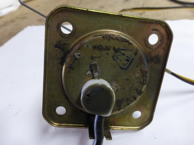
Here is what the outside of the plate looks like:
The metal tab that is spot welded to the outside of the plastic housing is where the ground is passed through. It is one of the most common failures. The spot weld fails and the tab does not make good contact to the plate or the solder conection from the wire to the tab fails (no ground, no pump). Sometimes you can attach a wire to the broken off tab or its wire and put a ring connector on it and put it on one of the four mounting studs instead of trying to resolder the tab to the plate.

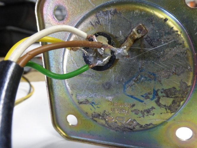
This is what it looks like inside the plastic (The previous owner had broken off the plastic and resoldered the wires and had put a huge gob of RTV over the wires to seal them. Don't know about the conductivity of RTV. Other than that. it should work).

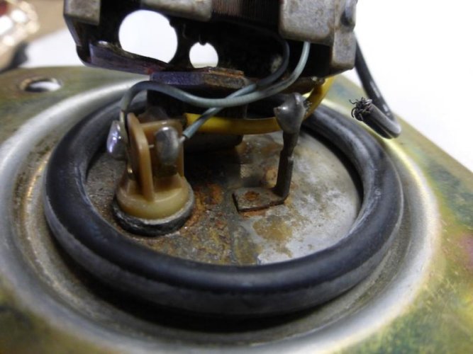
This is what the inside of the plate looks like:
Can you tell why this one does not work? (Black Ground wire) Sometimes the welded on tab breaks off the plate on the inside also.
Green wire from outside becomes the Yellow wire seen here (Pump +)
Brown wire from outside becomes Black wire seen here (Chassis Ground)
White wire outside becomes Blue wire on right (Low Fuel Light)
Yellow wire outside becomes Blue wire on left (signal for Fuel Gauge)

The Ground is used by all three circuits. It runs to the main Chassis Ground bundle on the left side of the upper frame frame tube underneath the fuel tank.
It is the ground for the Fuel Pump.
When the low fuel light switch connects the White (outside) wire to the ground, the light comes on.
The Fuel Gauge circuit puts a rheostat, controlled by the float, between the Yellow (outside wire) and the ground, thereby giving a variable input for the gauge.
If there is anything that I have left out or anything about this that you would like explained more, please post the question and I will update/elaborate further.


The four wires come from a 4 pin plug that is usually clipped to the right front of the tool tray or hanging near the right rear of the tank.
The wires on the plug that run to the sender plate are:
Fuel Pump Positive: Green
Chassis Ground: Brown
Low Fuel Light: White
Signal for Fuel Gauge: Yellow
IMPORTANT!!! As they pass through the plate the wires CHANGE COLORS!!! (Don't ask why!
 )
)Inside the tank:
Fuel Pump Positive: Yellow
Chassis Ground: Black
Low Fuel Light: Blue
Signal for Fuel Gauge: Blue
Here is what the outside of the plate looks like:
The metal tab that is spot welded to the outside of the plastic housing is where the ground is passed through. It is one of the most common failures. The spot weld fails and the tab does not make good contact to the plate or the solder conection from the wire to the tab fails (no ground, no pump). Sometimes you can attach a wire to the broken off tab or its wire and put a ring connector on it and put it on one of the four mounting studs instead of trying to resolder the tab to the plate.

This is what it looks like inside the plastic (The previous owner had broken off the plastic and resoldered the wires and had put a huge gob of RTV over the wires to seal them. Don't know about the conductivity of RTV. Other than that. it should work).

This is what the inside of the plate looks like:
Can you tell why this one does not work? (Black Ground wire) Sometimes the welded on tab breaks off the plate on the inside also.
Green wire from outside becomes the Yellow wire seen here (Pump +)
Brown wire from outside becomes Black wire seen here (Chassis Ground)
White wire outside becomes Blue wire on right (Low Fuel Light)
Yellow wire outside becomes Blue wire on left (signal for Fuel Gauge)

The Ground is used by all three circuits. It runs to the main Chassis Ground bundle on the left side of the upper frame frame tube underneath the fuel tank.
It is the ground for the Fuel Pump.
When the low fuel light switch connects the White (outside) wire to the ground, the light comes on.
The Fuel Gauge circuit puts a rheostat, controlled by the float, between the Yellow (outside wire) and the ground, thereby giving a variable input for the gauge.
If there is anything that I have left out or anything about this that you would like explained more, please post the question and I will update/elaborate further.


