• Welcome, Guest! We hope you enjoy the excellent technical knowledge, event information and discussions that the BMW MOA forum provides. Some forum content will be hidden from you if you remain logged out. If you want to view all content, please click the 'Log in' button above and enter your BMW MOA username and password.

    If you are not an MOA member, why not take the time to join the club, so you can enjoy posting on the forum, the BMW Owners News magazine, and all of the discounts and benefits the BMW MOA offers?

  • Beginning April 1st, and running through April 30th, there is a new 2024 BMW MOA Election discussion area within The Club section of the forum. Within this forum area is also a sticky post that provides the ground rules for participating in the Election forum area. Also, the candidates statements are provided. Please read before joining the conversation, because the rules are very specific to maintain civility.

    The Election forum is here: Election Forum

Can you help me figure out what's wrong?

Well, look at it this way, if you do wait until next year, you have a whole lot of time to acquire knowledge, diagrams, parts and tools you will need for the project, maybe even a place to work.

In some cases a bike can be put back on the road with just a fresh tank of gas a charge of the battery and off we go. Sadly, the longer the bike sits, the condition it is exposed to in storage, the degree of previous owner's disease, skill, parts availability, make some restorations untenable.

I have seen a lot of people spend large amounts of time and effort to put BMW airheads back on the road. In some cases like mine, sentimental issues keep me doing so. In my case, I have slowly over time acquired the knowledge and tools so the cost and frustration is not so great.

To be honest, I would be hard pressed to purchase a non running bike to put back on the road even with all the advantages I have, it can become a nightmare and or a money pit. My friend at his shop has a lot more experience with the later. LOL, I think my bikes are money pits but I love them.

I hate to be a pain but maybe now is a good time to seriously think about just what it is that you want to accomplish? For a heck of a lot less effort and in some cases less money, perfectly sound good running bikes can be found from /2 to 95. To restore a bike or in some cases to just get a bike running requires a lot of effort. The six million dollar question is would you rather be riding a bike or working on it? LOL, in my case, winter is the time I am happy to have a bike to work on because I can't ride, but boy howdy in the spring summer and fall, I don't want to be in the shop. St.

Well, as for cost... I got this bike for free. So far, the only money I've had to put into it is a pair of carburetor float gaskets. All the parts are there. That's why I took it, as being on disability and having a part time job, I don't really have money to throw around to buy a bike in better condition. So, I get old cast-offs and fix them and sell them, that's how I bought my first car. My last project is a 1989 Suzuki Intruder VS750 that I saved from an impound yard. It didn't need any engine work, just a fresh battery, paint, and new seat covers. I bought it for $300, and did all the work myself in the backyard. There's also a bit of a story behind it. Here's some before and after pictures.
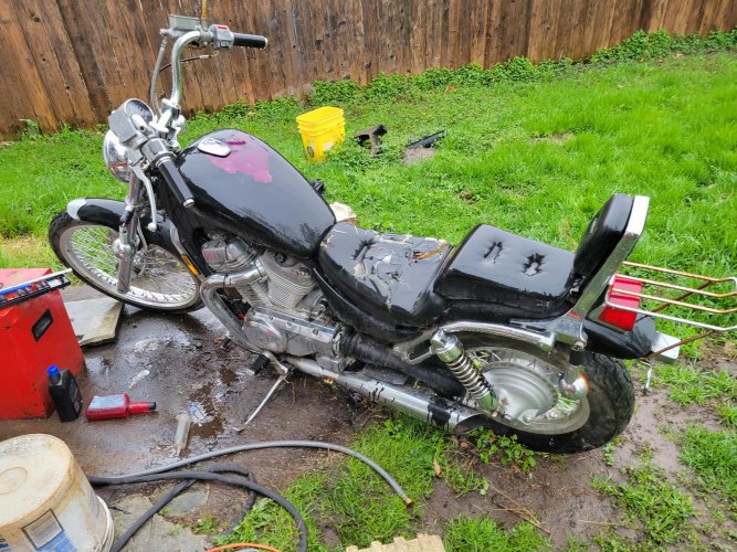
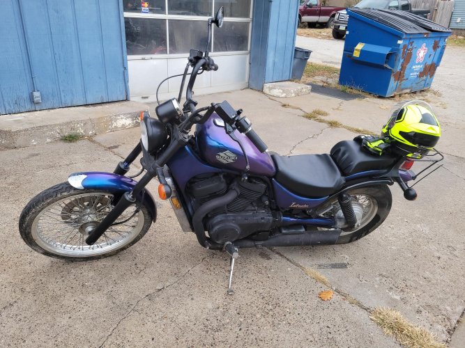
20220506_070949.jpg20221024_151808.jpg
 
You got it

LOL, okay, I am impressed, you got part of what it takes to restore an airhead. I know I keep nagging, go get a big walk in tent from craigslist or and outlet store to give you a place out of the wind and rain. Or get a friend to build you a shed.

More important, get the wiring diagrams and shop manuals.

It is great to get free non running cast offs and build them up to running. One of my best friends was very good at that. He never made a lot of money at it but his results were amazing. The Intruder looks pretty sharp.

LOL, you should look up kinterridge, on this forum, he just posted a thread "My next project". It looks like he does the same thing as you do. St.
 
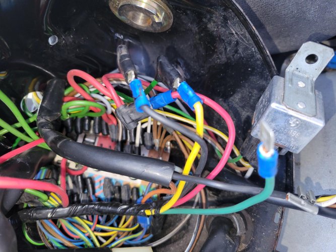
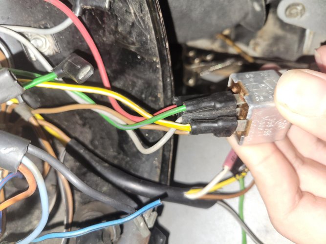
Here's the connections with the electric tape removed. The dark green wire at the bottom controls the instrument cluster illumination. None of the wiring diagrams seem to match this color wire. Looking at the wiring diagram confuses me and hurts my eyes. Like I can't make any sense of it. 1670015926452192188380356190364.jpg
 
That whole electrical taped mini harness is an addition possibly to accommodate the RT fairing. You may be able to remove it entirely if your goal is a naked or S-faired bike.
 
Insrument lights

Does this bike have the stock instrument cluster or did the previous owner install something else?
I don't know what the dark green wire is doing but it is NOT supposed to be the wire for stock instrument lighting. Stock instrument lighting is done with a gray/black wire coming out of the main harness, brown wire is ground.
Yellow wire: is only used from left handlel, low beam, goes to terminal 56b on the circuit board. From there it goes to the low beam headlight bulb. That is the only solid yellow wire used by BMW.
Red wires: one comes off the starter relay, one at terminal 30 on the ignition switch, the connect together a branch goes to terminal 30 on the headlight relay, the other side goes to terminal 30 on the circuit board. they may be all combined into one 90 degree factory plug because they plug into the circuit board. Also on terminal 30, another red wire goes to a clock if there is one. These are the only factory red wires.
A black wire goes from the headlight relay terminal 85 to ground on US models, On UK or Euro models this may be a brown wire going to terminal 31 on the circuit board.

Those wires with the blue crimp on ends are? They are a result of a previous owner who took the easy cheap way out to either fix something or as has been suggested to add on the RT fairing. I have seen the difference between the RT wiring and the S wiring and there is such little difference as to be negligible. The extra wires you have are due to lazy or stupidity, Now like a lot of victims of Previous owner's disease, you are stuck with it.

I really don't know what else to write, sorry, good luck, St.

Every bike I've ever owned has been previously owned, I'm no stranger to that. Mechanics, I can figure out. It's just wiring that confuses me.

So the dark green wire must equate to the gray-black; as with the dark green wire unplugged, none of the status lights on the cluster come on (brake failure, neutral, gen). The meter backlights still work.
 
Wiring diagram

As to the last message, maybe the green wire is the previous owner wired ground for the instrument cluster? If that is the case it should be brown, or a brown color combo wire. am sorry,

I can't help anymore until you get a wiring diagram, look things up, trace things out, perhaps then things will make sense to both of us. You don't have a friend who is more comfortable with wiring? St.

Maybe. I also hauled the bike inside so I can work on it at my leisure, regardless of temperature.

I'll probably pull the wires from the bucket and isolate that bundle, following it back to the instrument panel.
 
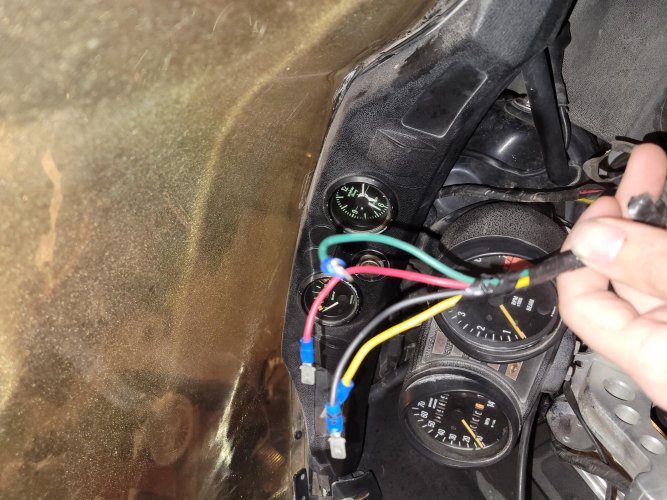
This mystery bundle connects to the clock and voltmeter.
Would it be safe to use a powered circuit tester?

The dark green wire connected with one of the two light green wires from the kill switch to power the lights on the instrument cluster. None of the wires lead to the cluster.
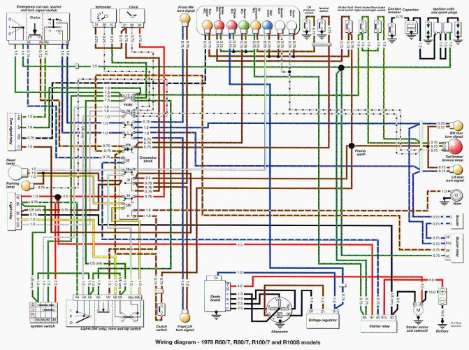
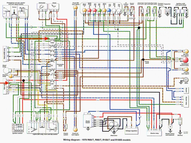
Is the kill switch wire supposed to have two 90 degree connectors? Here is the diagram I'm using.

16701118708657647012641879535231.jpg
16701145616004455369192239848082.jpg
78r100wire.jpg
 
Last edited:
Better

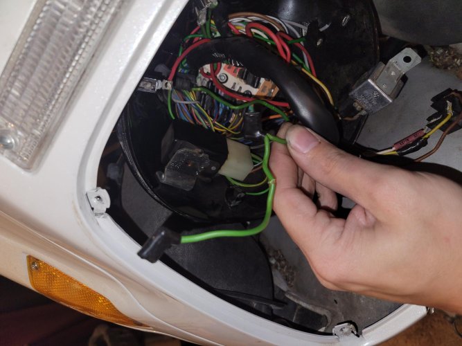
LOL, nice to have a protected work space. 78r100wire.jpgOkay, the tapped up bundle of wires in your hand in the first picture is garbage get rid of it.

The green wire in your hand with two wires going into a 90 plug could be the kill switch and the headlight relay wire going to pin 86 on the headlight relay. Or, it could be the ignition switch and headlight relay.

The clock has a red wire supplying power for the clock, gray/black for lights, brown for ground, green black for volts. The harness is available from EME.

The tachometer and speedometer lighting is gray/black. All the bulbs in the instrument cluster are grounded with a brown wire.


LOL, I am not quite sure what you mean by powered circuit tester? If you mean a continuity checker? Yes it is fine to use one. A test probe light and a voltmeter help as well.

I can't stress enough, work on one color group at a time, So for now, get rid of the tapped bundle of wires with the blue crimped ends.
Start with the green factory wires, like the ones in the second picture.

Yeah, wiring diagrams are an eyeful but really are not all that bad, for BMW.

Just a tip, one side of the circuit board kind of has uncontrolled power coming into it or going out. Those wires most likely are solid colors. They are main lines. Multi colored wires are in circuits controlled by switches or relays, and are auxiliary thing like the turn signal bulb and the parking light. Get the main lines sorted out first then worry about the auxiliary lines. Good luck. St.
 
LOL, nice to have a protected work space. View attachment 90103Okay, the tapped up bundle of wires in your hand in the first picture is garbage get rid of it.

The green wire in your hand with two wires going into a 90 plug could be the kill switch and the headlight relay wire going to pin 86 on the headlight relay. Or, it could be the ignition switch and headlight relay.

The clock has a red wire supplying power for the clock, gray/black for lights, brown for ground, green black for volts. The harness is available from EME.

The tachometer and speedometer lighting is gray/black. All the bulbs in the instrument cluster are grounded with a brown wire.


LOL, I am not quite sure what you mean by powered circuit tester? If you mean a continuity checker? Yes it is fine to use one. A test probe light and a voltmeter help as well.

I can't stress enough, work on one color group at a time, So for now, get rid of the tapped bundle of wires with the blue crimped ends.
Start with the green factory wires, like the ones in the second picture.

Yeah, wiring diagrams are an eyeful but really are not all that bad, for BMW.

Just a tip, one side of the circuit board kind of has uncontrolled power coming into it or going out. Those wires most likely are solid colors. They are main lines. Multi colored wires are in circuits controlled by switches or relays, and are auxiliary thing like the turn signal bulb and the parking light. Get the main lines sorted out first then worry about the auxiliary lines. Good luck. St.

Those two light green wire ends come from the kill switch,
is that stock?

Question... does the headlight low-high switch go to the green area on the board?
 
Last edited:
Stock

With the exception of the bundle of wires I told you to trash, it looks like what is left is stock. Switch wiring always terminates from the switch to the board for the most part. So yes, the green wire from the kill switch goes to the board, the extra plug may be for the headlight relay.
Follow the wire from the headlight dip switch on the wiring diagram, if it goes to the board it will show it on the diagram.

As I keep writing, the board is color coded and numbered to the proper wires, there are in some cases multiple spots in each colored section to plug in the proper wires. All green wires will end up there or on the item they originate at. You can't have a green wire plugged into any other spot.

From what I see in the pictures you have sent, most of the wiring looks like it is fine, that is a good thing, it could be worse. The previous owner added that bundle of wires for who knows what reason, they have to be tied into either another factory colored wire or a terminal on the board or a switch or relay or something. For example the wiring diagram shows if one of those bogus wires was tied into a terminal on the headlight relay, what the CORRECT wire for that terminal should be and where it should go to eliminate the bogus wire or wiring.

St.
 
I think the wiring diagram shows a black wire going to the headlight, and I saw one unplugged (which I think went to the beam selection switch), but there's no room on the relay. 20221209_171935.jpg
 
Yes, that relay looks like it's wired correctly if you have a three position lightswitch on the left handlebar (not the dimmer switch). Green/Gray comes from that switch if it's all the way on.

If you want the headlight on all the time, there's probably a random black wire in the headlight shell that you'd use to replace the Brown. You'd also run a wire from the ignition switch to replace the Green/Gray.

That said, those relays can be dodgy after 40+ years. I've replaced two out of three on the bikes I've revived.

If you have no headlight, but if you push the dimmer down and you get high beam, there's probably an issue with that relay. The high beam flash on the dimmer switch gets power directly from the junction board and not the relay.

The relay is $20ish from the dealer or your favorite online parts supplier. I haven't quite found one configured exactly right from NAPA but I haven't pushed the Gen Z counter help all that hard. "What's the VIN??"
 
Last edited:
With the exception of the bundle of wires I told you to trash, it looks like what is left is stock. Switch wiring always terminates from the switch to the board for the most part. So yes, the green wire from the kill switch goes to the board, the extra plug may be for the headlight relay.
Follow the wire from the headlight dip switch on the wiring diagram, if it goes to the board it will show it on the diagram.

As I keep writing, the board is color coded and numbered to the proper wires, there are in some cases multiple spots in each colored section to plug in the proper wires. All green wires will end up there or on the item they originate at. You can't have a green wire plugged into any other spot.

From what I see in the pictures you have sent, most of the wiring looks like it is fine, that is a good thing, it could be worse. The previous owner added that bundle of wires for who knows what reason, they have to be tied into either another factory colored wire or a terminal on the board or a switch or relay or something. For example the wiring diagram shows if one of those bogus wires was tied into a terminal on the headlight relay, what the CORRECT wire for that terminal should be and where it should go to eliminate the bogus wire or wiring.

St.

I've found that the red wire from around the bottom of the bucket, when connected to the red wire from the "junk" bundle, supplies power to the instrument cluster and ignition switch. I'm still not sure how the kill switch is wired backwards.

Actually, could it not be the kill switch selector (the off-run-off switch), but the start button itself? Also, the engine is no longer turning when I push the start button, no matter where the kill switch is. The starter relay is powered.
I would guess that somehow, the circuit is being completed when the button is pressed and the kill switch is set to off, but how, I don't know. I know little about electrics, only that they do not like to be messed with, and they will remind you of this very quickly.
 
Last edited:
Back
Top