• Welcome, Guest! We hope you enjoy the excellent technical knowledge, event information and discussions that the BMW MOA forum provides. Some forum content will be hidden from you if you remain logged out. If you want to view all content, please click the 'Log in' button above and enter your BMW MOA username and password.

    If you are not an MOA member, why not take the time to join the club, so you can enjoy posting on the forum, the BMW Owners News magazine, and all of the discounts and benefits the BMW MOA offers?

  • Beginning April 1st, and running through April 30th, there is a new 2024 BMW MOA Election discussion area within The Club section of the forum. Within this forum area is also a sticky post that provides the ground rules for participating in the Election forum area. Also, the candidates statements are provided. Please read before joining the conversation, because the rules are very specific to maintain civility.

    The Election forum is here: Election Forum

Can you help me figure out what's wrong?

Iowa

Well, you are a bit too far from me for me to show up to help, sorry. Cold doesn't bother me, hot does, LOL.

At the switch itself and where the bundle of wires enters into the headlight shell, those wires are color coded and should terminate on the circuit board. The green wire is a pain if I recall, it can have a junction somewhere inside that is not terminated on the board. Two of the green wires are.

Sorry, the photo didn't help much. Have you traces the green wire from the right switch and the ignition switch to terminal 15? Don't pay any attention to the scoctch lock crimp just confirm those two wires go there for now.

I will take another gander later today after I sort out a problem with my car at the dealership. Have you found a wiring schematic yet? I suggest the ones EME sells. In my case for now, I am working out of the latest version of the Haynes repair manual. I don't have an EME diagram on hand for the 77S, only for a 78.

Take a look in the MOA anonymous book (online or book) and see if perhaps there is a club member close by who might help, it is a long shot but hey, if you don't ask, or check, you will never know. It is too bad it is winter now and I am recovering from my accident and can't take a trip out to help. It has been a long time since I was in Iowa to visit my sister when she lived there. St.
 
Wiring problems

Possibly contact the the Iowa Air Marshel, Tina might know someone who could be helpful.
 
Green wire

Looking at the diagram agin I see a green wire connected to the right side of the fuse on the board at 15. This goes from there to the turn signal relay pin 49.
There is another green wire from the ignition switch 56 to the headlight switch in the left handlebar control.

At this point I can't help much more, you need to determine why the green wires in your picture are connected in the manner they are.

I suggest putting them back if possible onto the correct terminals

When you get a wiring diagram, I will be happy to see if I can help further. Attaching a diagram to the form may be possible but my taking a picture shrinking it to proper size kind of gives a hard to read sclkhematic.

Take a look at this guy's site, maybe he has a link or https://brook.reams.me/bmw-motorcyc...n-wire-harness-install-electrical-components/ that will help for now.

Good luck St,
 
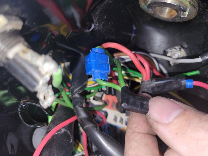
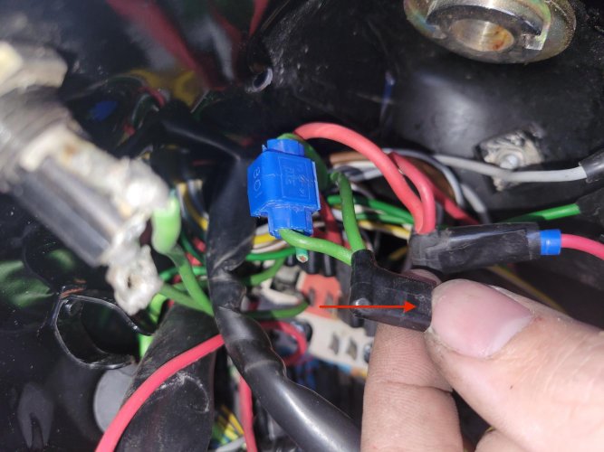
Found something. The kill switch wire runs to the black 90 degree plug. However, the blue crimper thing holds another green wire which runs to one of the plugs in the green area. Why was it doubled? The 90 degree connector was plugged in to this greenish wire with a spade connector.

I don't know why it uploads my pictures sideways.

1669753091576423697874241220575.jpg
16697531934487143880952773715216.jpg
16697533265354593908828150989409.jpg
 
Last edited:
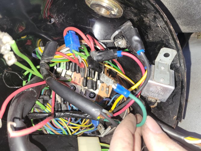
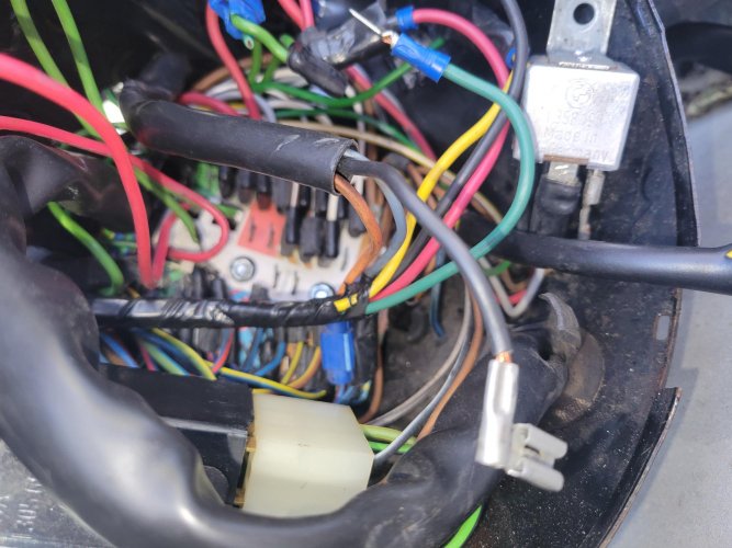
Here's a black wire that was unplugged, it shares a harness with an orange wire (that's blue crimper thing crimped to a blue wire with a red stripe), and a gray wire.

Also, this board doesn't have fuses in the regular places.
20221129_142913.jpg
 
Fuse

Yes, I saw your PO had wired two fuses and their holders in a non BMW way. I forgot to say, check those fuses to see if they are good? It really doesn't matter the fuses are not 100% original, look to see they are wired same as the original fuses were, the hot side on one side and the protected side on the other.

I have no idea why the PO did what he did or where those wires go now and that most likely is part of your problem.

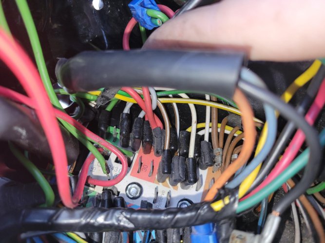
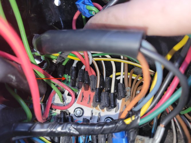
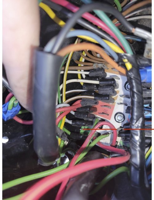
On your second picture I see one of the green wires plugged into a spot on the board in the wrong place and with the wrong kind of terminal end. I have marked it with red lines.

The terminal with the blue scotch lock crimp near your thumb should be plugged into the green section of the circuit board. That style insulated connector is a key tell tale of things plugged into the board, that is the type of factory connector. I marked the picture with an arrow where I think that plug should go. I can't help you much else.

Examine the bundles of wires entering into the headlight shell, factory done wiring is neat, tidy with proper connections similar to the one I pointed out. Any bundle of wire that is wrapped in electrical tape as is one I see and any wire with non stock connectors or crimp on dime store terminals is suspect. Trace things back to the source. Make sure things are plugged into the board in the proper colored spots. It is a jumping bundle of snakes working inside the headlight, not one of my favorite things to do, but you will have to dig into the non stock stuff, figure out what the intention was and in my best advice, put things back to stock or as close as you can. Before going any further, wait until you get your wiring schematic. Yes, things are color coded such but you really need a wiring diagram to figure out how things are wired and work. Good luck. St.

View attachment 16697531934487143880952773715216-2.pdf1669753091576423697874241220575.jpg16697531934487143880952773715216.jpg
 
Maybe a 'talk' with the previous owner would help to know the reason for all these modifications.

Can someone post a picture of his R100S?

My diagram does not match the colors of some wires which I see in the pictures.
 
One picture did not attach.

What should I do with the doubled-back green wire? I think there should be two things plugged into the green area on the board, and the kill switch wire you indicated is one of them. So the other one plugged into the green area should be unplugged, as it would be redundant.

I've tried looking fie a diagram of the '77 R100S, but I haven't been able to find one. It's all for the RS or RT, and the wire colors don't match. When I try looking at the diagrams, I get confused, anxious, and overwhelmed.

Unfortunately, the original owner is no longer with us, and the one who gave me the bike never messed with the wiring.
 
Last edited:
I've tried looking fie a diagram of the '77 R100S, but I haven't been able to find one. It's all for the RS or RT, and the wire colors don't match. When I try looking at the diagrams, I get confused, anxious, and overwhelmed.

Typically, diagrams for the '77 models or in general the /7 models would be applicable to the R100S. Obviously the RT/RS models have fairing mounted gauges, but the rest is pretty standard across that period of bikes.
 
Haynes

There are more than one wiring diagram for BMW bikes in existence. So far, the best ones I have found come from EME company. The one I have been using is out of the latest version of the Haynes repair manual. The older version of Haynes had the diagrams in black and white as are the original BMW wiring schematic/diagrams. You would have to search the internet for a copy of the original BMW diagram but be forewarned they are in German, black and white with a German wire color key. The repair manual Cylmer also has wiring diagrams.

Despite having a half dozen diagrams for my two bikes, there are occasions when BMW does a production wiring change and does not update the wiring diagram, this is rare but has caused problems for me in the past. As for Previous Owner's disease, that is a nightmare and I can understand the anxiety, confusion and frustration you are feeling however, it could be worse. The BMW wiring on your bike is really simple compared to other bikes and things. Yes, it is a pain in the ass to work inside the headlight shell, again, it could be worse. Don't Panic!

The green wire with the scotch lock blue crimp has a plug end on it that should plug into the circuit board. For each of the colored connections on the board there are multiple terminals so yes, more than one green wire can plug into that board location. BMW uses the same color wires for the S bike as does the RS and RT models. Multiple locations on the board allow accessories from BMW to be incorporated into the factory wiring without cutting into or breaking into the factory wiring. For example, my bikes have the Factory hazard flashers. The wiring bundle from the hazard switch enters the headlight shell and each of the wires in the hazard system plugs into the board in proper color order, sometime side by side with another system's wire.

I have no way of scanning or taking a photo of my wiring diagram that will convert into the file size this format requires that I believe would be readable. I can try later today but again, you need to purchase or find a working diagram, better yet, get a copy of the Haynes manual and Clymer Manual. LOL, they are difficult to decipher, especially the Clymer manual because they cover such a wide number of bikes from 70 to 95. But there is help there. Again, buy a diagram from EME.

It is difficult to read, interpret the pictures and write advice in the best of times, sorry, but without the bike here it is difficult for me to do much. I have given you the location and routing of the solid green wire as I see on my diagram. Trace it and make sure it is plugged into where it is supposed to go. Time to dive into the project, LOL, things don't get easier restoring a bike infected with Previous Owner's disease and that has sat for a long time is perhaps the biggest challenge in bike restoration. The reward can be great.

Good luck. St.
 
OK, I'll check those out when I get home.

The green wire that's in the crimper that loops back to the board isn't connected to anything else, it seems. It just served to hook the kill switch wire (which ran to that dark green wire), back into the board. So I think I can unplug that without issue. I'll have to get some 90 degree connectors and try to put the wires back in their original place. Also that bundle of wires (dark green, red, yellow, black), seem to go to the fairing clock and voltmeter.
Speaking of the voltmeter, I think there might be a bad ground or some corrosion somewhere, as the battery measures 12.8 on the multimeter, but only 10-11 on the fairing voltmeter.

Wiring diagrams in general are overstimulating to me. Too many tangles of lines leading to all different places. That's what gives me anxiety.
 
Cheer up

Cheer up, I am sorry I am being so hard on you. As I said it is not that bad. LOL, if you want anxiety, try using the BMW original wiring diagrams. Those were only in black and white with notation of wire color. The after market diagrams with color are so much easier to deal with and use, again a shameless plug for EME's version, they are in color and give terminal PIN numbers on such things as the ignition switch.

So, on your bike, it most likely was a S model, and the Previous Owner converted it to a RT. The RT fairing did not come into existence until 1979, so if your bike is older, you will need to use the wiring diagram for your year bike and for now, don't worry about auxiliary stuff like the clock and voltmeter.

The trick to wiring is to get the diagram, identify the issue and concentrate at one section of the wiring at a time. So, as I have said, there is a green wire from the ignition switch and other green wires. Look at the diagram and account for just the green wires the diagram shows, any extra green wires ignore especially those crimped on by the previous owner. Work one color of wire at a time, trace it from its start to finish. Check the proper colored wire is plugged into the proper colored terminal on the board, and on the proper Pin number location on something like the ignition switch or headlight relay.

Break things up into bite size pieces. BMW pretty much wired the bikes so that solid colored wires do important things, multicolored wires do less important things. Work first on the ignition system starting with the green wire on the ignition switch to where it goes on the diagram.

From what I can see, I don't yet see a need to be buying ninety degree terminals yet. DO NOT start cutting and making terminals until you KNOW what the circuit you are working on is doing, what color wires are in the circuit and if those wires are routed and plugged into the spots they are supposed to be in. Good luck, St.
 
Voltage meter

LOL, the factory voltage meters are indicators of voltage, they are not precise instruments, I have had one that was spot on with voltage readings taken by my voltage meter and another that was one volt low. Trust your voltmeter.

Oh yes, you should invest in a test probe light, and a continuity tester as well. St.

On some wires, the proper 90 degree ends appear to have been removed, in favor of spade connectors, which cannot link to the board. But yeah, I'm going to start with the kill switch wire and go from there. I'll unplug that other green wire, plug in the kill switch wire, then look at everything else. Unfortunately, the cold prevents me from working outside, so it may have to wait until next year.
 
Next year

Well, look at it this way, if you do wait until next year, you have a whole lot of time to acquire knowledge, diagrams, parts and tools you will need for the project, maybe even a place to work.

In some cases a bike can be put back on the road with just a fresh tank of gas a charge of the battery and off we go. Sadly, the longer the bike sits, the condition it is exposed to in storage, the degree of previous owner's disease, skill, parts availability, make some restorations untenable.

I have seen a lot of people spend large amounts of time and effort to put BMW airheads back on the road. In some cases like mine, sentimental issues keep me doing so. In my case, I have slowly over time acquired the knowledge and tools so the cost and frustration is not so great.

To be honest, I would be hard pressed to purchase a non running bike to put back on the road even with all the advantages I have, it can become a nightmare and or a money pit. My friend at his shop has a lot more experience with the later. LOL, I think my bikes are money pits but I love them.

I hate to be a pain but maybe now is a good time to seriously think about just what it is that you want to accomplish? For a heck of a lot less effort and in some cases less money, perfectly sound good running bikes can be found from /2 to 95. To restore a bike or in some cases to just get a bike running requires a lot of effort. The six million dollar question is would you rather be riding a bike or working on it? LOL, in my case, winter is the time I am happy to have a bike to work on because I can't ride, but boy howdy in the spring summer and fall, I don't want to be in the shop. St.
 
Back
Top