pauls1150
MOA #24991, south of Los Angeles
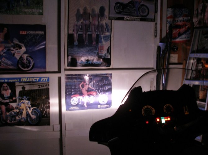
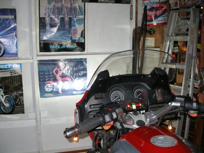
My stock halogen low beam pulls 55 watts ... this replacement LED assembly pulls 24 watts and is allegedly brighter, assuming the reflector gathers and aims the light properly.
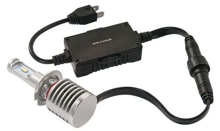
Pic from Cycle Gear (since it was on sale AND I had a coupon):
It was easy enough to remove my headlight’s rear cover without taking off any of the Tupperware®, as it jiggles out the lower right side, but there was No Way to get my fingers in there to actually accomplish the R&R. Got a couple of bloody scrapes trying.
Off came the bodywork, making lots more room to see and work, and more angles of attack.
Very careful back-and-forth wiggling gets the plug off the rear of the stock halogen bulb, and then unclip the wire bale (dual-finger spring clip) holding it in place. Note the orientation of the tabs around the ring; the “major” tab is at top center. The plug itself was in good condition; I have read a few times that the stock plug can melt or just crumble over time - NAPA sells a direct ceramic replacement that can be spliced into place.
Slipped the old bulb out and compared it to the new LED/heatsink assembly.
The Speedmetal part comes with its own mounting ring; this is pulled off the bulb’s collar and mounted first.
This ring also has several holes that match up with a little spring-loaded ball in the lamp base to create detents – this actually permits you to rotate the lamp in place, to align the LEDs to the headlight reflector assembly to get the best beam pattern.
On this new ring, I had to very slightly file down the top-center alignment tab (shown toward the left in the above pic) with a jeweler’s file – it was a little too big for the slot in my headlight’s mounting assembly. I had to reduce its width AND thickness just a hair, and I rounded off the sharp square corners of the tab.
Getting the new ring into place would be easier if I had made use of young elfin hands; it has to slip in “under” the stock plug and the bale, while maintaining proper alignment to seat into the socket holder. Once in place, it’s not a big deal to reattach the bale clips – this would be near impossible without taking off the bodywork, although some have done it by “feel” alone, from underneath. Not me...
The LED/etc. is then pushed into place, held by a tight O-ring and the detents in the base ring. I started with the LEDs pointing directly horizontal/sideways, since that is how the halogen bulb was aligned, and that “should” send the light toward the reflectors in the headlight assembly.
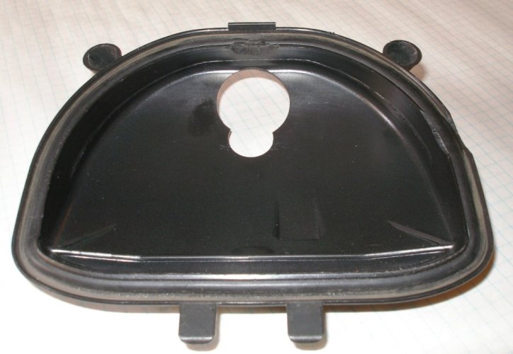
The heatsink is, of course, longer than the base of the stock bulb, and it requires airflow for cooling, so it’s necessary - I believe - to relieve (remove) some of the rear cover. The instructions do specifically say to provide airflow at the rear of the heatsink.
I had previously communicated with my local distributor for Cyclops (Brown’s in Pomona) about this, and there was definitely some uncertainty about whether a Cyclops LED would fit inside an RT’s rear cover plate. (I doubt it, but since I've not measured one, I don't "know".)
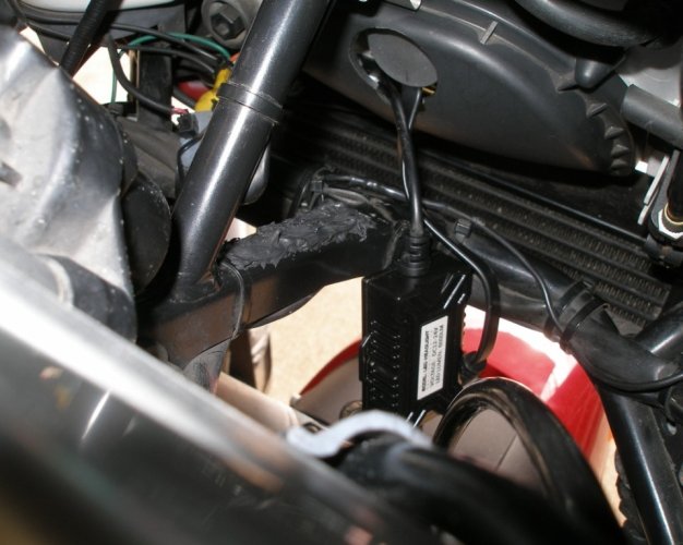
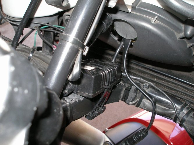
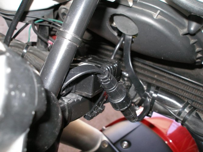
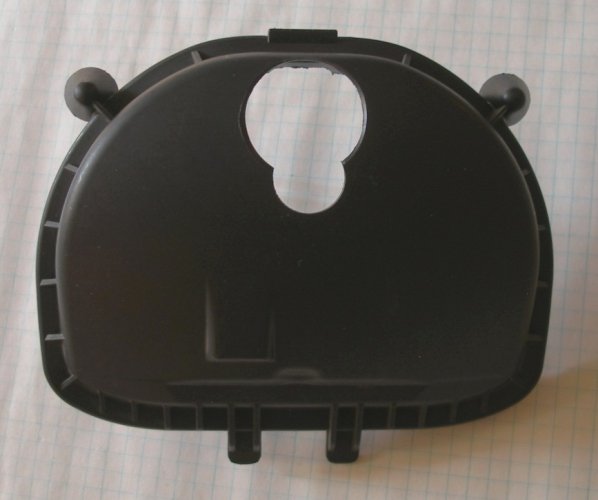
I figured I’d probably need two holes - one for the heatsink protrusion, and one for the driver (12-volt adapter) harness, which simply plugs in to the line between the “old” bulb socket and the LED; the driver will not fit inside the cover. I tried.
Using “step” drills, I made the first hole directly behind where the heatsink is: measuring straight down from the center of the tab that the holding clip latches on to, I made my first centerpunch at 1 inch. I then made a second centerpunch 1 inch directly below that. A step at a time, I enlarged both holes to ¾ of an inch and lightly sanded the edges to smooth them out.
Then I put the cover back into place to see what aligned, or didn’t.
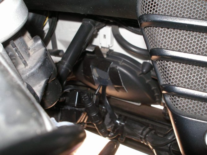
The upper hole was very close to being centered behind the heatsink – woo-hoo! The heatsink itself measures about 1.20 inch diameter, so I enlarged that hole to 1.25 inch (after a quick trip to Harbor Freight to pick up a bigger step drill). This took the upper edge of the hole right up to the edge of the cover, and also “broke through” to the smaller ¾ inch hole below it (for the driver harness), but this is not a problem.
Pic from Cycle Gear (since it was on sale AND I had a coupon):

It was easy enough to remove my headlight’s rear cover without taking off any of the Tupperware®, as it jiggles out the lower right side, but there was No Way to get my fingers in there to actually accomplish the R&R. Got a couple of bloody scrapes trying.
Off came the bodywork, making lots more room to see and work, and more angles of attack.
Very careful back-and-forth wiggling gets the plug off the rear of the stock halogen bulb, and then unclip the wire bale (dual-finger spring clip) holding it in place. Note the orientation of the tabs around the ring; the “major” tab is at top center. The plug itself was in good condition; I have read a few times that the stock plug can melt or just crumble over time - NAPA sells a direct ceramic replacement that can be spliced into place.
Slipped the old bulb out and compared it to the new LED/heatsink assembly.
The Speedmetal part comes with its own mounting ring; this is pulled off the bulb’s collar and mounted first.
This ring also has several holes that match up with a little spring-loaded ball in the lamp base to create detents – this actually permits you to rotate the lamp in place, to align the LEDs to the headlight reflector assembly to get the best beam pattern.
On this new ring, I had to very slightly file down the top-center alignment tab (shown toward the left in the above pic) with a jeweler’s file – it was a little too big for the slot in my headlight’s mounting assembly. I had to reduce its width AND thickness just a hair, and I rounded off the sharp square corners of the tab.
Getting the new ring into place would be easier if I had made use of young elfin hands; it has to slip in “under” the stock plug and the bale, while maintaining proper alignment to seat into the socket holder. Once in place, it’s not a big deal to reattach the bale clips – this would be near impossible without taking off the bodywork, although some have done it by “feel” alone, from underneath. Not me...
The LED/etc. is then pushed into place, held by a tight O-ring and the detents in the base ring. I started with the LEDs pointing directly horizontal/sideways, since that is how the halogen bulb was aligned, and that “should” send the light toward the reflectors in the headlight assembly.
The heatsink is, of course, longer than the base of the stock bulb, and it requires airflow for cooling, so it’s necessary - I believe - to relieve (remove) some of the rear cover. The instructions do specifically say to provide airflow at the rear of the heatsink.
I had previously communicated with my local distributor for Cyclops (Brown’s in Pomona) about this, and there was definitely some uncertainty about whether a Cyclops LED would fit inside an RT’s rear cover plate. (I doubt it, but since I've not measured one, I don't "know".)
I figured I’d probably need two holes - one for the heatsink protrusion, and one for the driver (12-volt adapter) harness, which simply plugs in to the line between the “old” bulb socket and the LED; the driver will not fit inside the cover. I tried.
Using “step” drills, I made the first hole directly behind where the heatsink is: measuring straight down from the center of the tab that the holding clip latches on to, I made my first centerpunch at 1 inch. I then made a second centerpunch 1 inch directly below that. A step at a time, I enlarged both holes to ¾ of an inch and lightly sanded the edges to smooth them out.
Then I put the cover back into place to see what aligned, or didn’t.
The upper hole was very close to being centered behind the heatsink – woo-hoo! The heatsink itself measures about 1.20 inch diameter, so I enlarged that hole to 1.25 inch (after a quick trip to Harbor Freight to pick up a bigger step drill). This took the upper edge of the hole right up to the edge of the cover, and also “broke through” to the smaller ¾ inch hole below it (for the driver harness), but this is not a problem.


Last edited:

