• Welcome, Guest! We hope you enjoy the excellent technical knowledge, event information and discussions that the BMW MOA forum provides. Some forum content will be hidden from you if you remain logged out. If you want to view all content, please click the 'Log in' button above and enter your BMW MOA username and password.

    If you are not an MOA member, why not take the time to join the club, so you can enjoy posting on the forum, the BMW Owners News magazine, and all of the discounts and benefits the BMW MOA offers?

  • Beginning April 1st, and running through April 30th, there is a new 2024 BMW MOA Election discussion area within The Club section of the forum. Within this forum area is also a sticky post that provides the ground rules for participating in the Election forum area. Also, the candidates statements are provided. Please read before joining the conversation, because the rules are very specific to maintain civility.

    The Election forum is here: Election Forum

Coil wiring questions

brant914

New member
Hello, I hope everyone is having a good monday

another question, and I tried the search feature first.. but no answers were specific enough

my bike is a 1971 R75/5
early wiring harness (new) with no fuses.
I imagine all of the dual coil models are likely similar.

today I'm trying to figure out how I'm supposed to wire the dual coil

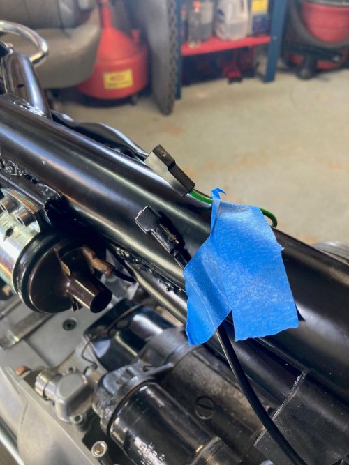
I have the black wire coming from the points/condenser
and the green wire which ultimately touches the on switch, and rear brake switch

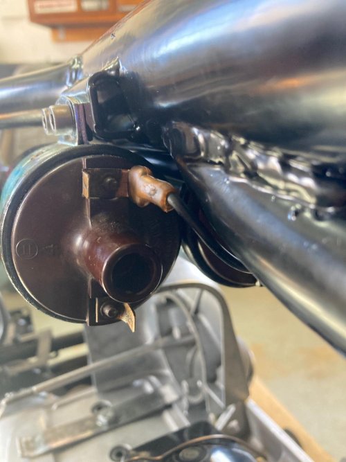
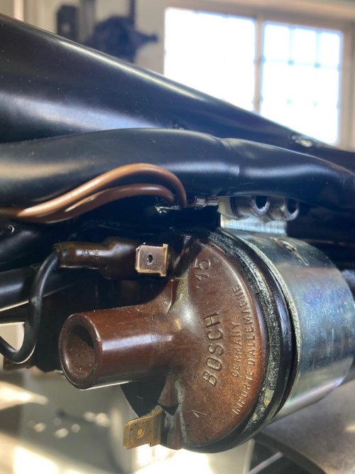
on the coils themselves
they are marked 1, and also 15
I'm not familiar which of those numbers corresponds to plus or minus (like a coil I'm familiar with in a car)

and I'm also confused with the jumper wire that goes from one coil to the other

I mounted them with the 15 up on both sides of the bike
and then jumped from a 15 double post, to the other side

1) is there a second jumper wire?.... do I have a double post broken on one of my coils?
2) is the jumper wire supposed to jump the #1 marking rather than the #15?
3) in the clymer manual it talks about the coils grounding through the mounting brackets... I painted mine... the original stickers were under the bracket before... hindering a ground.
Should I strip the paint from my coils due to needing that ground path?
4) does the black wire (points/condenser) go to post 15 or 1 ?
5) same question for the green wire (I may need to rotate my coils)

sorry for all of the questions today
brant
 

Attachments

  • bmw1.jpg
    bmw1.jpg
    278.2 KB · Views: 143
  • bmw2.jpg
    bmw2.jpg
    232.8 KB · Views: 144
  • bmw3.jpg
    bmw3.jpg
    261.7 KB · Views: 142
I'm usually wrong, but I think you can reverse the 1 and 15. That is, enter on one coil at 1, connect the 15 terminal to the 1 terminal on the second coil, and then 15 connects to the points. It's just a continuous wire from 1 to 15 on each coil. The diagram shows soldered joints at the coil but the wiring harness has female terminals that connect to the coil terminals.
 
that looks cool.
my previous owner must have gotten rid of that...
he had been into the headlight wiring... everything was spliced, and even household wire twists were used....

thus the brand new harness from BMW
but it did not include a fuse like that.

what circuit/wire did the factory put that on?

brant
 
Mine may have been added but it was probably part of the lighting circuits. Still they may be a good thing to add.
 
Question (well, two actually) re: Kurt's response, for the ignition wizards:
If the wiring at terminals 1 and 15 are reversed, that reverses the direction of the built-up charge in the primary windings of the coil.
When the points open and that charge is inductively passed to the secondary windings, won't that result in the spark jumping from the the ground electrode of the spark plug to the center tip of the plug, instead of the typical tip-to-grounded electrode? And, is this actually an acceptable condition?
 
I really appreciate everyone's time and advice.
I fixed my wiring last night.

final question... regarding the ground path
has anyone painted their coils ? (like I just did)

the factory finish was black when I got them.. the stickers peeling...
but maybe that finish was conductive? for ground...
seemed kinda like a powdercoat was used when new... but mine were rusty.. and the finish somewhat compromised.

I guess I should have tested conductivity before I painted.
anyone have experience or advice?


thanks in advance
brant
 
I don't believe the coil bodies have to be grounded; the spark wiring is complete with what is shown above. (Though grounded bodies "may" reduce RFI, Radio Frequency Interference, or wide-band static noise, if you have a radio.)
They may live longer if they're heat-sinked to a large metal mass, like the frame.
 
Last edited:
Paul, that's why I wasn't too sure. But in the simplest terms, the coil consists of a winding of wire around a smaller winding of wire. Current flow in the outside wiring just induces energy in the inner winding. I'm not sure I see the difference in which way the current flow. But, I'm glad to learn more.
 
I don't believe the coil bodies have to be grounded; the spark wiring is complete with what is shown above. (Though grounded bodies "may" reduce RFI, RF interference, or wide-band static noise, if you have a radio.)
They may live longer if they're heat-sinked to a large metal mass, like the frame.

I had an ignition issue several years ago that turned out to be a broken coil mount. I welded it up and that fixed it. Never a problem after that (since ‘91). I always thought the issue was that the coil wasn’t grounded through it’s mount.
 
I checked a few wiring diagrams on Snowbum's site...none show a ground connection to the body of the coil.
 
Gary, I'm bamboozled... "maybe" you had a poor ground somewhere else, and the repair compensated for it by being in parallel? :scratch

An ignition coil is just a transformer; sometimes, if one side of the primary winding is directly connected to one side of the secondary winding, that makes it an "autotransformer".
There is such a thing as electrically conductive paint, and maybe there is continuity between the "low" side of the coil and the case? Dunno, I've never bothered to check that on a "Good" ignition coil ... maybe somebody can do a measurement for us?
 
Weaker spark if coils wired backwards

Question (well, two actually) re: Kurt's response, for the ignition wizards:
If the wiring at terminals 1 and 15 are reversed, that reverses the direction of the built-up charge in the primary windings of the coil.
When the points open and that charge is inductively passed to the secondary windings, won't that result in the spark jumping from the the ground electrode of the spark plug to the center tip of the plug, instead of the typical tip-to-grounded electrode? And, is this actually an acceptable condition?

I have heard that coils wired with their polarity reversed will work but they will generate a weaker spark but i never asked why. This article goes into it a bit. https://austinmotorvehicleclubqld.org/blog/2020/3/4/ignition-coil-polarity
 
/5 coils are grounded

I just finished completely rewiring a '73 R60/5 so this is still fresh in my mind.

The coils are grounded with a brown wire. The factory wiring diagram is confusing. It shows the ground connection hanging out in the middle of the diagram, no where near the coils. The connection itself is tagged as "7" in the diagram and is labeled "Ground connection on frame for ignition coils."
 
What diagram are you using? What does the legend say for #7? I suspect the legend says "frame ground" which means a suitable, unpainted, nearby frame location.
 
Back
Top