• Welcome, Guest! We hope you enjoy the excellent technical knowledge, event information and discussions that the BMW MOA forum provides. Some forum content will be hidden from you if you remain logged out. If you want to view all content, please click the 'Log in' button above and enter your BMW MOA username and password.

    If you are not an MOA member, why not take the time to join the club, so you can enjoy posting on the forum, the BMW Owners News magazine, and all of the discounts and benefits the BMW MOA offers?

  • Beginning April 1st, and running through April 30th, there is a new 2024 BMW MOA Election discussion area within The Club section of the forum. Within this forum area is also a sticky post that provides the ground rules for participating in the Election forum area. Also, the candidates statements are provided. Please read before joining the conversation, because the rules are very specific to maintain civility.

    The Election forum is here: Election Forum

Setting a Hall Sensor Plate (Ignition Timing) - '96 R1100RT

bwanajames

New member
Greetings All,

I've got a '96 R1100RT and as a preventative measure, have decided to replace the Hall Sensor. Now, my question is: How to best adjust the sensor base plate for proper ignition timing?

Before removing the old Hall sensor, I made a scribe mark next to the baseplate so at the very least, I could return the new one to the same position as the old. But, curious if there was a more accurate method, I snooped around the forums and found one suggesting that the timing/base plate position could be set using a voltmeter as described below:


"After replacing the sensor plate you will need to check the ignition timing, you can do this with the test rig above or with a voltmeter.

To test with a volt meter, plug the sensor plate in to the bike and switch on the ignition. Put the negative clip to a good earth on the frame and the positive probe to the Orange wire in the coupler (upper sensor). Watch the meter as you slowly turn the engine clockwise (viewed from the front).

Timing is correct when the voltage drops to zero with the OT (TDC) timing mark central in the window."


While this sounds simple enough, when my voltmeter needle drops, it is nowhere close to the OT (TDC) mark regardless of the baseplates position within the allowable latitude of the adjusting slot(s).

Has anybody tried and can verify this technique?

Additional Background:
1. The '96 1100's have, I understand, the 2.2 Motronic. While the 2.4 Motronic can be timed with the fuel pump cycle method, the 2.2 Motronic apparently cannot.

2. Before someone recommends the Dana Hager test box method, I've gone down to Radio Shack, purchased the components (which the clerk was kind enough to assemble) but unfortunately the LED's never illuminated. (Obviously an assembly error, but it looks good per the schematic...). So with a malfunctioning test box, I'm eager to validate the voltmeter method.

3. I understand some have had some success with a standard timing light (with initial advance being very close to the "S" mark...) if the rpms are at/below 1,000 (before the Motronic starts manipulating things...). But this method strikes me as problematic if the rpms aren't just right, so I haven't tried it.

Thanks,
Jim
The timing light works fine at 1000.
You will see any advance right above that.
 
I am not 100% positive - only 99% positive so take note:

But i believe that you can time the HES with the fuel pump coming on with the 1100 and Motronic 2.2. With any luck either Roger or Anton will correct me if I am wrong.

Also, using a timing light and keying on the full advance "F" mark works.
 
I don't know about the voltmeter method but I'm surprised that the fuel pump method doesn't work.

For me, when I changed mine, the scribe method was perfect. I'd start there.

Until the engine is fully warmed up, the Motronic will change timing at idle on the 1150 so I assume it's the same on the 1100. Static timing is the way to go.

I'll look for some more info.
 
Greetings All,

I've got a '96 R1100RT and as a preventative measure, have decided to replace the Hall Sensor. Now, my question is: How to best adjust the sensor base plate for proper ignition timing?

Before removing the old Hall sensor, I made a scribe mark next to the baseplate so at the very least, I could return the new one to the same position as the old. But, curious if there was a more accurate method, I snooped around the forums and found one suggesting that the timing/base plate position could be set using a voltmeter as described below:


"After replacing the sensor plate you will need to check the ignition timing, you can do this with the test rig above or with a voltmeter.

To test with a volt meter, plug the sensor plate in to the bike and switch on the ignition. Put the negative clip to a good earth on the frame and the positive probe to the Orange wire in the coupler (upper sensor). Watch the meter as you slowly turn the engine clockwise (viewed from the front).

Timing is correct when the voltage drops to zero with the OT (TDC) timing mark central in the window."


While this sounds simple enough, when my voltmeter needle drops, it is nowhere close to the OT (TDC) mark regardless of the baseplates position within the allowable latitude of the adjusting slot(s).

Has anybody tried and can verify this technique?

Additional Background:
1. The '96 1100's have, I understand, the 2.2 Motronic. While the 2.4 Motronic can be timed with the fuel pump cycle method, the 2.2 Motronic apparently cannot.

2. Before someone recommends the Dana Hager test box method, I've gone down to Radio Shack, purchased the components (which the clerk was kind enough to assemble) but unfortunately the LED's never illuminated. (Obviously an assembly error, but it looks good per the schematic...). So with a malfunctioning test box, I'm eager to validate the voltmeter method.

3. I understand some have had some success with a standard timing light (with initial advance being very close to the "S" mark...) if the rpms are at/below 1,000 (before the Motronic starts manipulating things...). But this method strikes me as problematic if the rpms aren't just right, so I haven't tried it.

Thanks,
Jim
Jim,
After looking it over and comparing the procedures, try the following:

--rotate the engine until the bike is at TDC.
--loosen the HES plate and rotate it fully clockwise, the voltage should be low 0V.
--slowly rotate the plate counterclockwise until the voltage pops high.
--compare to original position. If it looks good you're done.

As the slotted window still glued to the pulley?
RB
 
Factory TDC Index?

I don't know about the voltmeter method but I'm surprised that the fuel pump method doesn't work.

For me, when I changed mine, the scribe method was perfect. I'd start there.

Until the engine is fully warmed up, the Motronic will change timing at idle on the 1150 so I assume it's the same on the 1100. Static timing is the way to go.

I'll look for some more info.

Gents,

Thanks for the input. But to simply life, and based on Roger's endorsement, I decided to try the "scribe" method. (I only wish I'd been a bit more aggressive with my awl, as my mark is rather faint...). But in the process, I made an observation that may be worth sharing.

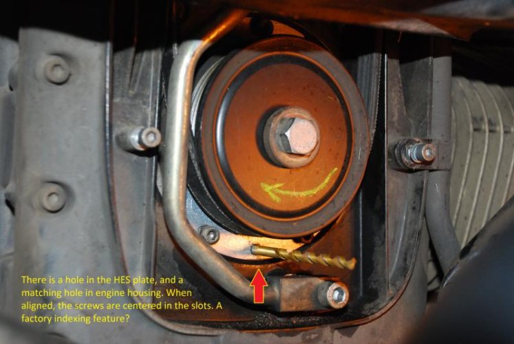
I noticed that there is a small hole in the HES baseplate at the 6:00 o'clock position. Immediately behind it, there is an identically sized hole in the engine case. When these two holes are aligned (reason for the drill bit) the securing screws are precisely centered in the baseplate slots. To me, this seems like more than a coincidence.

From a manufacturing perspective, assemblers probably don't want fool with rotating baseplates. So it makes sense to have corresponding index holes. Could this be a convenient way to duplicate the original factory setting?

Roger:
Yes, the tabbed firing window is still glued (indexed) to the crank pulley.

Fuel Pump Method: 2.4 vs. 2.4 Motronic
I've got a 2000 R1100RS with a 2.4 Motronic and the fuel pump cycle method does work on it. But, on the '96 R1100RT with the 2.2 Motronic, the fuel pump cycling method does not work. The pump does indeed cycle while slowing turning the engine by hand with the ignition on, but when it does, it's nowhere near any of the flywheel marks. Others on this forum with similar vintage RT's have been unable to use the fuel pump method, so I can only assume the 2.2 Motronic has something to do with it.

RT_Hall Sensor Index Hole Alignment_Notes.jpg
 
Gents,

Thanks for the input. But to simply life, and based on Roger's endorsement, I decided to try the "scribe" method. (I only wish I'd been a bit more aggressive with my awl, as my mark is rather faint...). But in the process, I made an observation that may be worth sharing.

I noticed that there is a small hole in the HES baseplate at the 6:00 o'clock position. Immediately behind it, there is an identically sized hole in the engine case. When these two holes are aligned (reason for the drill bit) the securing screws are precisely centered in the baseplate slots. To me, this seems like more than a coincidence.

From a manufacturing perspective, assemblers probably don't want fool with rotating baseplates. So it makes sense to have corresponding index holes. Could this be a convenient way to duplicate the original factory setting?

Roger:
Yes, the tabbed firing window is still glued (indexed) to the crank pulley.

Fuel Pump Method: 2.4 vs. 2.4 Motronic
I've got a 2000 R1100RS with a 2.4 Motronic and the fuel pump cycle method does work on it. But, on the '96 R1100RT with the 2.2 Motronic, the fuel pump cycling method does not work. The pump does indeed cycle while slowing turning the engine by hand with the ignition on, but when it does, it's nowhere near any of the flywheel marks. Others on this forum with similar vintage RT's have been unable to use the fuel pump method, so I can only assume the 2.2 Motronic has something to do with it.

View attachment 50012

I think it would be very interesting to know where bmw is typically setting the hes plate on the 11xx. On my 2000 r1100rt it came with the plate as fully advanced as the bolts would allow (plate hits right bottom bolt before left bottom bolt when rotated CCW).
 
I noticed that there is a small hole in the HES baseplate at the 6:00 o'clock position. Immediately behind it, there is an identically sized hole in the engine case. When these two holes are aligned (reason for the drill bit) the securing screws are precisely centered in the baseplate slots. To me, this seems like more than a coincidence.

View attachment 50012

Interesting. However if that was the intention why slot the holes in the HES? They could have made the plate non adjustable. I'm in the same boat after replacing my '04's HES.
 
Interesting. However if that was the intention why slot the holes in the HES? They could have made the plate non adjustable. I'm in the same boat after replacing my '04's HES.

Setting the plate position (timing) on an 1150 is very easy.
Remove the timing plug and turn the engine CW until you find the OT mark (TDC)
Turn on the ignition and move the HES plate until you hear the fuel pump cycle.
This brings you close.
Now turn the engine CCW a few degrees and approach the OT mark slowly.
When the timing is set correct the fuel pump will cycle when the mark hits the middle of the inspection hole.
Tighten the 3 allen screws and you are done.

Note: this method will not work for the 1100's
 
When I first purchased my '97 RT, the plate was at about the center of the adjustment (I didn't note the holes' alignment).
After break-in and with experimentation, it ran a little better with the plate all the way advanced, and the plugs still looked good.
I figured the computer was adjusting the timing on an as-needed basis anyway.
 
I use the fuel pump method with all of them (1100 and 1150). It works for me. But I don't use the OT mark; I use a dial indicator on the piston to observe actual OT.
 
Setting a Hall Sensor - Update

BMW Ignition Timing Box (Hall) - Mine.jpg

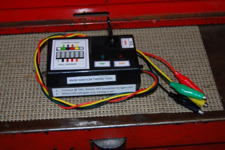
As mentioned in the opening post, I attempted to build a Dana Hager ignition timing test box, which the helpful salesperson at Radio Shack was kind enough to assemble. Sadly, I never got it to work. Learning the LED's are polarity-sensitive, I wondered if it was incorrectly assembled. So, I bought fresh components, and assembled them myself (above).

Initially, it didn't work either. But then, I rotated the engine with a wrench EVER SO SLIGHTLY... And the LEDS lit up! Apparently, I only THOUGHT I had the OT timing marks properly aligned through the peep hole.

So it appears, if you are minutely off the flywheel OT mark, you can rotate the HES base plate through the full range of the slots and not have the test box LED's light up. (Yes, perhaps the original test box was fine...).

Where I'm going with this is: Perhaps Anton's method of determining TDC with a dial indicator is superior to the peep hole method...

Jim
 
Same old problem- 90k miles on a 1997 R1100RS Sensor OK! Pulley broke.

I posted another thread about my symptoms, hoping it helps someone diagnose the condition. MY cycle was misfiring only around 4000 rpm.
Turns out I had the split/broken pulley. Welded it back together, but installing a new timing HES since I bought and shipped it, in any case. Having trouble with the voltmeter method.
From the above post:

VAfter looking it over and comparing the procedures, try the following:

--rotate the engine until the bike is at TDC.
--loosen the HES plate and rotate it fully clockwise, the voltage should be low 0V.
--slowly rotate the plate counterclockwise until the voltage pops high.
--compare to original position. If it looks good you're done.


As the slotted window still glued to the pulley?
RB

Did this and it is misfiring worse! Starts, can rev, but dies coughing and misfiring. Have my volt probe stuck in the orange wire, am getting 12v when I turn crank, and 0v near TDC. Confused by plate. Trying to move it clockwise and CCwise and don't seem to get any reaction from the voltmeter. A little frustrated that the adjustments are so tiny! Plate doesn't seem to move more than 2-3 mm in either direction.
My next step is to remove pulley, get belt out of way, use pin at TDC (and wiggle it to see how fine the rotation is), and really study the position of the HES base plate. (Tired of putting tank on, taking tank off to test the running engine)

Old thread, but I'm asking if anyone can vouch for using voltmeter method, and any tips on how to do it beyond the simple instructions above?
 
Awesome, tons of good stuff posted but; the assumption is all the mechanical are almost or nearly new, Story:

My neighbour spent years, close to a decade, my guess, building a '67 Stang. Had the short block done. It's a beautiful car.
I have heard this car start four/five times, for years, before it catches and has good fire. I finally had enough and chatted with him.

Choke angle, on spec. Idle timing, on spec. Advance was a nice 60 degrees, on spec.

Gave me the car, cold, opened the choke angle a little. First start, OK, we got a stumble and some labouring.

Advance idle timing to 10, let it get cold, first start and away. Still won't do a burnt out.

Find out later, short block rebuild didn't include the timing sprockets, only the chain. Changed the sprockets to a gear set, listened to what the engine wanted, set choke and timing that and she can do one serious burnt out.

Specs be good, listening to what your engine wants is better.
 
My experience

Some of the above descriptions have two different sources of timing sensors.
If you scribe a mark on your sensor plate, and have it rebuilt/rewired, you can put it back where you found it.
Mine was a brand new unit from the seller on Amazon. I did make marks on the old one. I outlined the edge of the base plate with a Sharpie so I could put new one in same spot. It didn't really work.
I had to cut open the weather cover over the wiring harness, to get access to the wire loom clip, and probe the orange wire. The other probe wire went to neg. terminal. With tank off and belt hanging out of way, I found TDC and pinned the flywheel. The base plate on sensor was still difficult to rotate and adjust. It sits behind the pulley, and just parts of its edges are able to reach. I could finally find a forward CW position, which read 0v on the voltmeter. Then brought it backwards. CCW, until I could just get approx. 11.5 volt. Carefully, slightly wiggled it some more top and bottom. Tightened down (stripped one screw), adjusted alternator, restored tank and started it. Seemed pretty rough with dying and misfires, but had a chance to spin up a road and it got better and better.
After finishing the adjustment of new unit, the holes and edges of the new unit did not match up with any of my original marks.

In the end, I still have a problem with my cycle but the new ignition system at 90,000 miles feels good. Getting a new HES is a very doable project for a wrencher. The vids didn't capture on film any of the finer techniques of rotating that baseplate, or working with the voltmeter and TDC. I kept reading this thread and experimenting until it became clear.
 
Last post on this subject. Swear.

A quick question just occurred to me. Doing some other sensor replacements, and thinking about the wiring/connectors.
The root cause of the HES sensor failure is the wiring. Something about bad formulations in the insulation during an early period of time of manufacture.
Why does this not affect other wiring and other systems? Should we be wary of all the wiring (mine is 1997)?
 
It was not bad formulation. It was misapplication by Bosch.

Any insulation must meet the temperature requirement of the application.
In the case of the old style hall sensor plates the insulation spec was only 80c (176f). (Later units past late '02 did get an upgraded spec)
The temperature behind the plate at the splice point against the engine is far higher than that especially idling in heavy traffic. 250f+
This causes breakdown to eventually dust.
It should be noted the actual wires on the sensors themselves are a high temperature silicone spec and do not fail.

Rewiring with a high temperature Teflon or Kapton cable will eliminate any future problems.
 
Last edited:
View attachment 58547

As mentioned in the opening post, I attempted to build a Dana Hager ignition timing test box, which the helpful salesperson at Radio Shack was kind enough to assemble. Sadly, I never got it to work. Learning the LED's are polarity-sensitive, I wondered if it was incorrectly assembled. So, I bought fresh components, and assembled them myself (above).

Initially, it didn't work either. But then, I rotated the engine with a wrench EVER SO SLIGHTLY... And the LEDS lit up! Apparently, I only THOUGHT I had the OT timing marks properly aligned through the peep hole.

So it appears, if you are minutely off the flywheel OT mark, you can rotate the HES base plate through the full range of the slots and not have the test box LED's light up. (Yes, perhaps the original test box was fine...).

Where I'm going with this is: Perhaps Anton's method of determining TDC with a dial indicator is superior to the peep hole method...

Jim

For anyone else building one of these boxes it is easy to test. Just turn is on and connect the green and the yellow leads to ground and the LEDs should illuminate. If they do not then you have a construction issue.
 
Back
Top