• Welcome, Guest! We hope you enjoy the excellent technical knowledge, event information and discussions that the BMW MOA forum provides. Some forum content will be hidden from you if you remain logged out. If you want to view all content, please click the 'Log in' button above and enter your BMW MOA username and password.

    If you are not an MOA member, why not take the time to join the club, so you can enjoy posting on the forum, the BMW Owners News magazine, and all of the discounts and benefits the BMW MOA offers?

  • Beginning April 1st, and running through April 30th, there is a new 2024 BMW MOA Election discussion area within The Club section of the forum. Within this forum area is also a sticky post that provides the ground rules for participating in the Election forum area. Also, the candidates statements are provided. Please read before joining the conversation, because the rules are very specific to maintain civility.

    The Election forum is here: Election Forum

evaporative emission control system hose connections

aapasquale

aapasquale
I recently took all the fiberglass panels off my 1994 r1100rs which I just purchased to have them repainted. Of course, in order to remove the gas tank, the fuel and evaporative emission control lines had to be diconnected from the charcoal canister. In my mad dash to the finish line I failed to mark how the evaporative emission lines are to be reconnected. I have looked all over creation for a diagram or explanation, but so far have only discovered that I should have marked them first. This is not helpful......does anyone have a clue about this? Your help would be greatly appreciated.

Tony
 
I recently took all the fiberglass panels off my 1994 r1100rs which I just purchased to have them repainted. Of course, in order to remove the gas tank, the evaporative emission control lines had to be diconnected from the charcoal canister. In my mad dash to the finish line I failed to mark how the evaporative emission lines are to be reconnected. I have looked all over creation for a diagram or explanation, but so far have only discovered that I should have marked them first. This is not helpful......does anyone have a clue about this? Your help would be greatly appreciated.

Tony
 
There are two hoses: the water drain from the filler neck and the internal vent. You should test them by blowing into them, but normally the drain line has X-X-X markings. That one gets connected to the line going to ground, while the other goes to the canister.

When removing the tank, the easiest way to keep track of them (once you know they are right) is to leave one plastic connector on the tank and one on the bike.
 
The hose to the solenoid fits the center post. The solenoid is nearby. The other hose disappears so it can get to the fuel tank, and that's the side hose. If you have a "drain" hose it's to the nipple on the other end.
 
Last edited:
Helpful, But

Could someone please post some photos of the exact routing from the solenoid purge valve back to the throttle bodies?
My whole system has been removed and I want to route the hoses, the Tee correctly as original.
Thanks, Ibjman
 
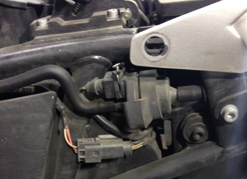
Here you go. You can see that the canister hose runs outside the frame rail.

canister1.jpg

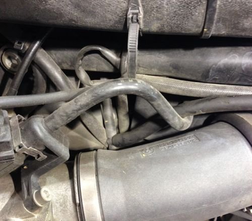
The hose enters from the right and goes to the T behind the throttle body.

This is on an 1150 but it's a better example than the 1100 I had available.

canister2.jpg
 
Back
Top