• Welcome, Guest! We hope you enjoy the excellent technical knowledge, event information and discussions that the BMW MOA forum provides. Some forum content will be hidden from you if you remain logged out. If you want to view all content, please click the 'Log in' button above and enter your BMW MOA username and password.

    If you are not an MOA member, why not take the time to join the club, so you can enjoy posting on the forum, the BMW Owners News magazine, and all of the discounts and benefits the BMW MOA offers?

  • Beginning April 1st, and running through April 30th, there is a new 2024 BMW MOA Election discussion area within The Club section of the forum. Within this forum area is also a sticky post that provides the ground rules for participating in the Election forum area. Also, the candidates statements are provided. Please read before joining the conversation, because the rules are very specific to maintain civility.

    The Election forum is here: Election Forum

LED Frustrations

G

GREGFUESS

Guest
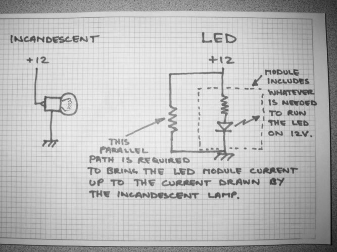
Does anyone else have this problem? More significantly, does anyone else have a solution? I installed LED turn indicators on my 2008 CANBus outfitted 2008 K1200S. The replacement bulbs came with resistors, but the turn indicators flash way faster than the stock.

I replaced the incandescent brake light with LED, and the light is so bright without the brake applied, that applying the brake makes the light no brighter than without the brake applied. This is obviously not a good situation, so I installed the STOPAlert designed for use with LED brake lights, but the flasher is still cycles very fast compared to the STOPAlert for incandescents.

I really like the brightness of the LEDs, but not the rapid flashing, and not that the tail light is no brighter with the brake applied. Any recommendations welcome.

Greg

Oh, yes and of course, the LEDs lit up the dash, but the local dealer said not to worry about the warning signs on the dash.
 
Off the top of the head - If the resistor or resistor network is adjustable you may want to go to a higher rating.

Another solution is adding resistor in line (seires) between the load and the resistive network provided
 
I agree. You probably just need a larger resistor. You can add one in series with each indicator light.

Same may apply to the break issue as well, if you replaced the running light and the break light with LEDs.

If the rear running light is out, then the electrical system will run the break light at low power. The LED light will be bright even at low power (because of the circuit inside it).

Put a 6 Ohm 10 Watt Resistor in series with the running light, and the break light should work.

NOTE: Resistors get very hot. You don't want it to be touching any plastic (or wires). Attach the resistor to something metal (aluminum) which gets a lot of airflow. This will act as a heat sink, but you still may be better off leaving the running light. The 7 Watt bulb will get hot, but the fixture is designed to take it.
 
To work properly with the BMW ZFE, resistors are required in series and in parallel with your LEDs.

LEDs use very little current and also have low voltage drops. Connecting an LED directly to a 12 volt source will blow the LED because the current supplied will be excessive. Resistors are required in series to limit the current and protect the LED. This will be true whether or not the LED is used with a device like the ZFE.

The ZFE looks at current draw to detect bulb failures. The current through an LED is too small and the ZFE interprets this as a burned out bulb, hence your dash warning light. When you activate your turn signals, the high flash rate is another indication of a burned out bulb. Older mechanical flasher relays did this by design since the current through the relay determined the flash rate. Modern electronic flashers are required to do this by US federal lighting specifications to give the look and feel of a mechanical flasher. To increase the current in the LED circuit, a resistor is required in parallel with the LED and its current-limmiting resistor.

Parallel or in Sieries. Does it matter in this case? I usually say series becuase that's a slightly easier install.
 
Parallel or in Sieries. Does it matter in this case? I usually say series becuase that's a slightly easier install.

It would matter, wouldn't it? Wouldn't the electricity go through the least resistance resistor if in parallel?

This discussion is a great help. Any recommendation for what size resistor to use?

Greg
 
LED turn signals require different flasher relays than incandescent indicators. You can futz around with resistors if you want, but it's a stone-aged way to do things.

superbrightleds.com sells various flasher relays for short money.
 
I have seen specific kits made for CANBUS bikes. All were complete replacement units for the existing lights or a replacement module to place inside the turn signals completely replacing the existing socket and reflector assembly. There is no way to change the flasher module either to compensate since that function is built into the CANBUS controller. The problem with the tail/brake light, is the original uses a singal filament bulb and the CANBUS varies the voltage to increase the brightness for the brake light.
 
Parallel or in Sieries. Does it matter in this case? I usually say series becuase that's a slightly easier install.

A series resistor is used to limit the current through the LED so as not to burn it out. A parallel resistor is used to increase the total current through the circuit to fool the ZFE. The functions are opposite each other.
 
There really aren't any aftermarket fit-the-same-socket LEDs that represent much in the way of engineering. It's really just an exercise in fitting K-Mart quality do-dahs and no wonder there are problems.

When you start to see the "big boys," i.e Phillips, Osram, etc., in the market, then you'll have something. Don't hold your breath.
 
You might also check with you dealer about a ZFE reflash. I remember reading somewhere that the ZFE can be reprogrammed to work with LEDs.
 
LED turn signals require different flasher relays than incandescent indicators. You can futz around with resistors if you want, but it's a stone-aged way to do things.

superbrightleds.com sells various flasher relays for short money.

Thanks, I wrote an email to superbrightleds asking for their thoughts. In the mean time, any advise on adding resistors would be appreciated. In parallel, series? resistor strength?

Regards

Greg
 
There really aren't any aftermarket fit-the-same-socket LEDs that represent much in the way of engineering.

5 watt Luxeon LEDs in 1156 and 1157 bulb-base configurations are slightly brighter than incandescent versions of the same thing. Right now, they are the brightest plug-in LED replacements on the market. This could change tomorrow.

In my case, I'm recovering watts from my tail lights to use for heated gear. It's not much, but it helps.
 
Light Buddies turn indicators with StopAlert

These LEDs come with "ballast" or something, and were purchased from Pirate's Lair. They do not work as indicated, and the response I got is that I have installed them incorrectly. But after reviewing the instructions repeatedly, I cannot see how else they would be installed.

So I am asking about resistors, since the high rate of flash cycle is annoying, and getting it back to stock would be good.

Any recommendations on resistors? I am hesitant to remove them, since Pirate's Lair has already said that they would not accept the return, and I like the idea of the LED's if they would work.

The BMW dealer here in Houston, as well as a former BMW mechanic with a generic shop indicated that they were really not interested in trying to fix the problem, because the fix takes lots of time and they basically do not need the headaches. Apparently LEDs on motorcycles are a general problem. NOW I know!

Any recommendations appreciated.

Greg
 
Hi Greg:

You should be able to use the LEDs if you're willing to do some messing around to find a resistor value.

What you need to do is add a parallel resistance to the LEDs in order to bring the current back up to what it was with the incandescent bulbs. Somewhat defeats the purpose of lower power but I'm sure that bike has lots.

If your bulbs are #1156 they draw about 2A each.

Get yourself a cheapo Horror Fright meter(with a DC 10A feature) if you don't already own one and measure the current required by 1 bulb at 13.7V. Let's say it's 2A. You now know you need to draw 4A for the pair of turn signals on one side of the bike.

Now determine the current drawn by a pair of LEDs on one side of the bike, let's guess it's 1A, I don't know.

Now you know you have to provide a parallel path for the missing 3A.
Resistance = 13.7volts/3Amps or 4.5 ohms.

To determine the wattage of this resistor (13.7V^2)/4.5 Ohms = 41.7W. Technically you could divide the power by two since the duty cycle is 50% but I'd go big to distribute the heat better.

Now you need to get two resistors, one for each side and wire them to the existing turn signals left and right before anything the LEDs came with. As stated above, they will get warm so mount them accordingly. Due to the intermittant nature of turn signal usage they may never get hot but worst case design is always best.

I hope this helps, if you do it please post the results. I'd like to know how much current the LEDs draw.
 
I found this site to be a big help calculating resistor values:

http://led.linear1.org/led.wiz

Measure the existing resistance with the incandescents, then plug in the intended LED, power source (12v), etc. and it will give you the resistor value you need to add (I soldered the resistors to the positive lead).
 
Last edited:
I decided to pop in an LED tailpiece on my F8ST. Turns out the Canbus tests resistance on all bulbs on the bike and even though there are numerous LED's on the replacement board the resistance is still lower than the incandescent so the bulb test fails and I get a bulb failure indicator on the OBC.

Not a major big deal but I have not been able to figure out the resistance difference nor obviously a solution. So the board sits idle.
 
If you add a couple of jumper wires (in series ) to your exisitng resistor and the buld load you caan get a range of resistors you could plug them in one at a time until you get to a resistance value the computer will accept.

A little clugey (sp?) but it will get you where you need to be and then once the value is identified replace it with an same as or better value.

Default to higher value if you can't get common resistor value that will work.
 
Some clarification

Just in case anyone is attempting to measure LED module resistance. These are semiconducting devices which don't behave like resistors. Measuring them with a meter will not provide useful information applicable to this problem.

I suppose it's possible the bike is measuring resistance, if so, there will be trouble fooling that feature into thinking there is an incandescent load. It's far more likely that the bike is monitoring load current.

This schematic shows what you need to do to match the LED current to the incandescent current.

My previous post(#15) tells how to determine the value.
 

Attachments

  • BikeLED.jpg
    BikeLED.jpg
    135.7 KB · Views: 117
Back
Top